Learn what industrial winterization is and the essential basic design requirements for winterization systems in cold climates.
Tag: System Design
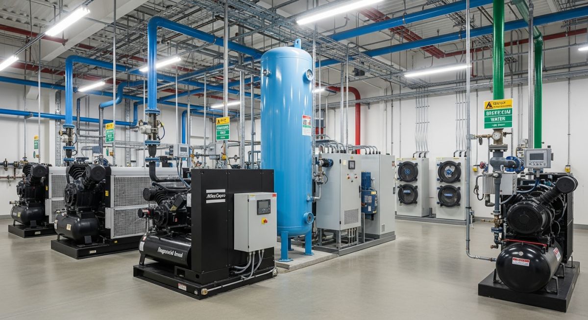
Learn the fundamentals of compressed air system design, key components, working principles, and optimization strategies for industrial efficiency.
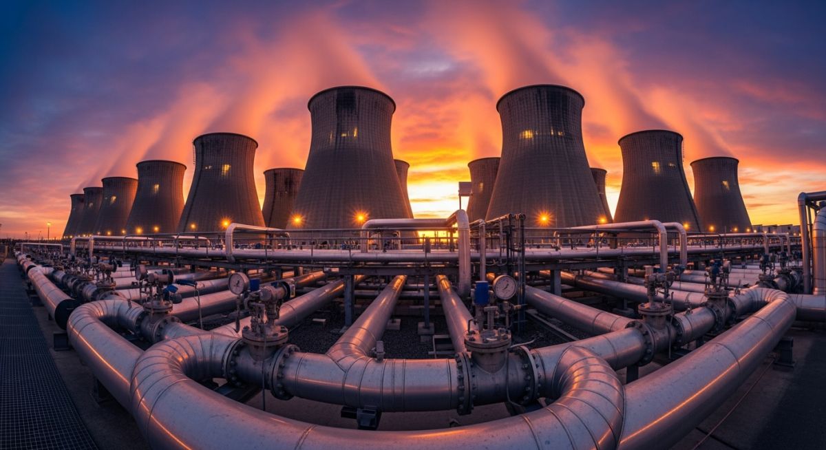
Master Cooling Water System Design with our 2026 engineering guide. Learn about recirculation, flow rate calculations, and ASME standards for industrial utility.