Master B31.3 Pressure Relieving Reaction Load allowable stress. Compare occasional loads vs PSV reaction forces in CAESAR II for 2026 standards.
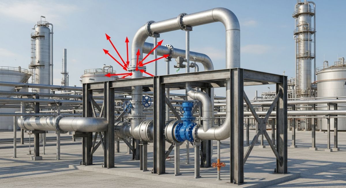
Master B31.3 Pressure Relieving Reaction Load allowable stress. Compare occasional loads vs PSV reaction forces in CAESAR II for 2026 standards.

Master Water Pumping Station Piping Stress Analysis using flexible sleeve couplings. Learn CAESAR II modeling, AWWA C219 standards, and thrust restraint.

The Hidden Cause of Recurring Flange Leaks: A Refinery Case Study Flange Leak Diagnostics The