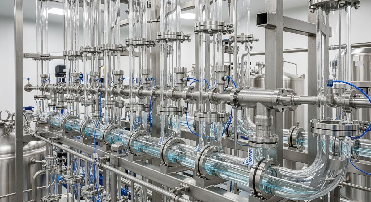
Engineering Verified Updated: 2026 What is a Glass Piping System? Engineering Design and Considerations 2026 A Glass Piping System is a specialized industrial piping solution primarily constructed from borosilicate glass 3.3 to provide unparalleled corrosion resistance and visibility in aggressive chemical environments. Quick Definition: Glass Piping System A Glass Piping System utilizes high-grade borosilicate glass components to transport corrosive fluids and high-purity media. It is preferred in pharmaceutical and chemical sectors due to its universal chemical resistance, smooth non-leachable surface, transparency for process monitoring, and ability to withstand temperatures up to 200°C. "While most engineers fear glass due to brittleness, a properly engineered Glass Piping System with floating supports is often the only viable solution for ultra-pure chemical synthesis." — Atul Singla, Epcland Architect Engineering Knowledge Check Question 1/5 Next Question Restart Quiz In This Technical Guide Fundamental Features of Glass Piping Systems Key Advantages of Glass Piping in Chemical Processing Technical Specifications for Glass Piping System Design Critical Methods for Supporting Glass Pipes Glass Piping System Installation Best Practices Glass Piping System Failure Case Study: Thermal Shock Analysis Maintenance and Inspection of Glass Piping Systems Fundamental Features of Glass Piping Systems The core of any modern Glass Piping System lies in the utilization of Borosilicate Glass 3.3. This specific material grade is engineered to provide a unique combination of mechanical strength and chemical inertness. Unlike standard soda-lime glass, the high silica and boric oxide content ensure that the system remains stable under aggressive chemical attack and rapid temperature fluctuations. A critical feature of the Glass Piping System is its linear coefficient of expansion. At approximately 3.3 x 10⁻⁶ K-1, it is significantly lower than carbon steel or stainless steel. This low expansion rate is vital for maintaining joint integrity during thermal cycling. Furthermore, the fire-polished smooth surface prevents the accumulation of scale and bio-films, making it the preferred choice for high-purity pharmaceutical applications. Figure 1: Exploded view of a typical Glass Piping System coupling and PTFE sealing interface. Key Advantages of Glass Piping in Chemical Processing When evaluating material selection for corrosive environments, a Glass Piping System offers advantages that metallic or plastic alternatives cannot match. The most prominent is universal corrosion resistance. Borosilicate glass remains unaffected by almost all known chemicals, except for hydrofluoric acid, hot phosphoric acid, and strong caustic solutions at high concentrations. Unmatched Transparency for Process Monitoring In complex chemical synthesis, visual confirmation of flow, color changes, or phase separation is invaluable. The transparency of a Glass Piping System allows operators to identify blockages, monitor crystallization, and ensure reaction completion without the need for expensive inline sensors. This visibility reduces downtime and enhances the safety of the entire plant. Superior Thermal Shock Resistance Despite being a brittle material, a well-designed Glass Piping System exhibits remarkable thermal shock resistance. Because of its low expansion properties, it can handle sudden temperature differentials of up to 120°C. This allows for rapid heating or cooling cycles in batch reactors without the risk of catastrophic failure, provided the supports are correctly engineered to allow for longitudinal movement. Technical Specifications for Glass Piping System Design Engineering a Glass Piping System requires strict adherence to pressure and temperature envelopes. Typically, the maximum allowable working pressure (MAWP) decreases as the pipe diameter increases. For instance, a DN 25 pipe may be rated for 4 bar, whereas a DN 300 pipe may only be rated for 1 bar. Standard components in a Glass Piping System are designed to operate within a temperature range of -40°C to +200°C. However, the true limiting factor is often the coupling's gasket material. PTFE is the industry standard due to its chemical compatibility, but specialized Viton or silicone gaskets may be used for specific cryogenic or high-vibration scenarios. Critical Methods for Supporting Glass Pipes The engineering of a Glass Piping System differs fundamentally from metallic systems due to the material's high modulus of elasticity and lack of ductility. Supports must be designed to eliminate point-loading and bending moments. According to ASME B31.3 Chapter VII for non-metallic piping, supports for brittle materials must provide continuous protection against vibration and external impact. Effective Glass Piping System support strategies utilize "stress-free" hangers. These are typically oversized rings lined with 3mm to 5mm of EPDM rubber or cork. The goal is to ensure the pipe is "floating" within the support, allowing for thermal expansion without creating friction-induced stress at the glass surface. Nominal Bore (DN) Max Support Distance (mm) Max Pressure (Bar) Expansion (mm/m @ 100°C) DN 25 1250 4.0 0.33 DN 50 1500 4.0 0.33 DN 100 2000 2.5 0.33 DN 300 2500 1.0 0.33 Glass Piping System Installation Best Practices Successful deployment of a Glass Piping System depends on the precision of the installation phase. Unlike steel pipes that can be forced into alignment, glass components must achieve perfect axial alignment before the couplings are tightened. Misalignment creates a permanent bending stress that significantly reduces the safety factor of the Borosilicate glass 3.3 components. Gasket and Coupling Torque Specifications Standardizing the torque on couplings is non-negotiable. Over-tightening leads to flange breakage, while under-tightening results in leaks during thermal shock resistance testing. Engineers should reference ISO 3585 for glass properties and use calibrated torque wrenches. Thermal Expansion Calculation for Glass Piping The total longitudinal expansion (ΔL) in a Glass Piping System can be calculated using the formula: ΔL = L0 × α × (T1 - T0) L0: Original length of the pipe (mm) α: Linear expansion coefficient (3.3 × 10⁻⁶ K-1) T1: Operating Temperature (°C) T0: Ambient Installation Temperature (°C) Relevant Engineering Standards To ensure global compliance and safety, every Glass Piping System should be designed in accordance with: ASME B31.3: Process Piping (specifically Category M fluids and non-metallic rules). EN 1595: Pressure Equipment - Borosilicate glass 3.3; General rules for design, manufacture and testing. ISO 4704: Glass plant, pipeline and fittings - Glass components with a nominal bore of 15 to 1000 mm. Glass Piping System Thermal Expansion Calculator Calculate the longitudinal growth of your Borosilicate 3.3 pipeline based on process temperature differentials. Original Pipe Length (L0) in Meters Temperature Difference (ΔT) in °C Total Linear Expansion (ΔL) 0.00 mm Calculate Expansion Reset Note: Uses the standard Borosilicate 3.3 expansion coefficient (α) of 3.3 x 10⁻⁶ K-1. Don't miss this video related to Glass Piping System Summary: Master Piping Engineering with our complete 125+ hour Certification Course: ...... ✅ 2500+ VIDEOS View Playlists → JOIN EXCLUSIVE EDUCATION SUBSCRIBE Glass Piping System Failure Case Study Project Data Application: Hydrochloric Acid (HCl) Recovery Material: Borosilicate 3.3 (DN 150) Operating Temp: 140°C Issue: Recurring fractures at the elbow joints. Failure Analysis Post-mortem inspection revealed that the Glass Piping System was installed using rigid carbon steel U-bolts without cushioning. During rapid startup, the pipe was unable to expand longitudinally, creating a localized bending moment exceeding the glass's modulus of rupture (60 N/mm2). Engineering Fix The rigid hangers were replaced with spring-loaded floating supports lined with PTFE. Furthermore, ASME B31.3 compliant bellows were integrated into the Glass Piping System design to absorb axial movement, reducing mechanical stress on the borosilicate components by 85%. Lessons Learned Never use metal-to-glass contact; always employ rubber or PTFE liners. Thermal expansion in a Glass Piping System must be calculated and accounted for using flexible bellows or expansion loops. Support spacing must strictly follow DN size charts to prevent sagging. Frequently Asked Questions about Glass Piping Systems What are the pressure limitations for a Borosilicate 3.3 Glass Piping System? Pressure limitations for a Glass Piping System are size-dependent. Smaller diameters (DN 15-50) can typically handle up to 4 bar (approx. 58 psi), while larger diameters (DN 300+) are usually limited to 1 bar (approx. 14.5 psi). The temperature also de-rates this pressure capacity. How do you manage thermal expansion in a glass process plant? Managing thermal shock resistance is critical. This is done by using floating supports that allow free longitudinal movement and incorporating dedicated expansion joints, such as PTFE bellows or expansion loops, within the Glass Piping System layout. Can glass piping be used for abrasive slurries or high-velocity fluids? While glass is extremely hard, it is not ideal for abrasive slurries at high velocity as erosion can occur, reducing the wall thickness and creating localized weak points. The Glass Piping System excels in highly corrosive, non-abrasive liquid and gas transfer. Does ASME B31.3 cover the design and installation of glass piping? Yes, ASME B31.3 Chapter VII provides mandatory requirements for non-metallic piping. Specific guidance on allowable stresses, joining methods, and support for brittle materials like Borosilicate glass 3.3 is outlined within this standard. Conclusion: The Future of Corrosion-Resistant Systems Designing a Glass Piping System requires a nuanced engineering approach that balances its phenomenal chemical resistance and transparency with the inherent limitations of a brittle material. By strictly adhering to standards like ASME B31.3 and ISO 3585, and implementing correct stress-free support mechanisms, engineers can deploy a highly reliable, long-lasting piping solution for the most demanding chemical and pharmaceutical processes. The 2026 engineering landscape continues to favor specialized, high-purity solutions, ensuring the Glass Piping System remains a critical component in modern process plants. 📚 Recommended Resources: Glass Piping System Read these Guides 📄 Comprehensive Guide to PVC Pipe Sizes: PVC Piping Dimensional Chart (2026) 📄 What is a Fiberglass Pipe Shaver? Working & Specs (2026 Guide) 📄 Sight Glasses for Oil and Gas: The Definitive 2026 Engineering Guide –> 📄 The Root Cause of Persistent Leaks: How We Overcame Flange Face Damage Leakage in Process Piping 🎥 Watch Tutorials Glass Pipes II Types II Applications II Properties #epcland Mastering Pipe & Various Configurations in Oil & Gas Projects | Ultimate Quiz ASTM A312 vs. ASTM A358: Demystifying Stainless Steel Pipe Standards | Which One to Choose?