Discover the essential instrumentation engineering deliverables required for successful execution of oil and gas industry projects.

Discover the essential instrumentation engineering deliverables required for successful execution of oil and gas industry projects.
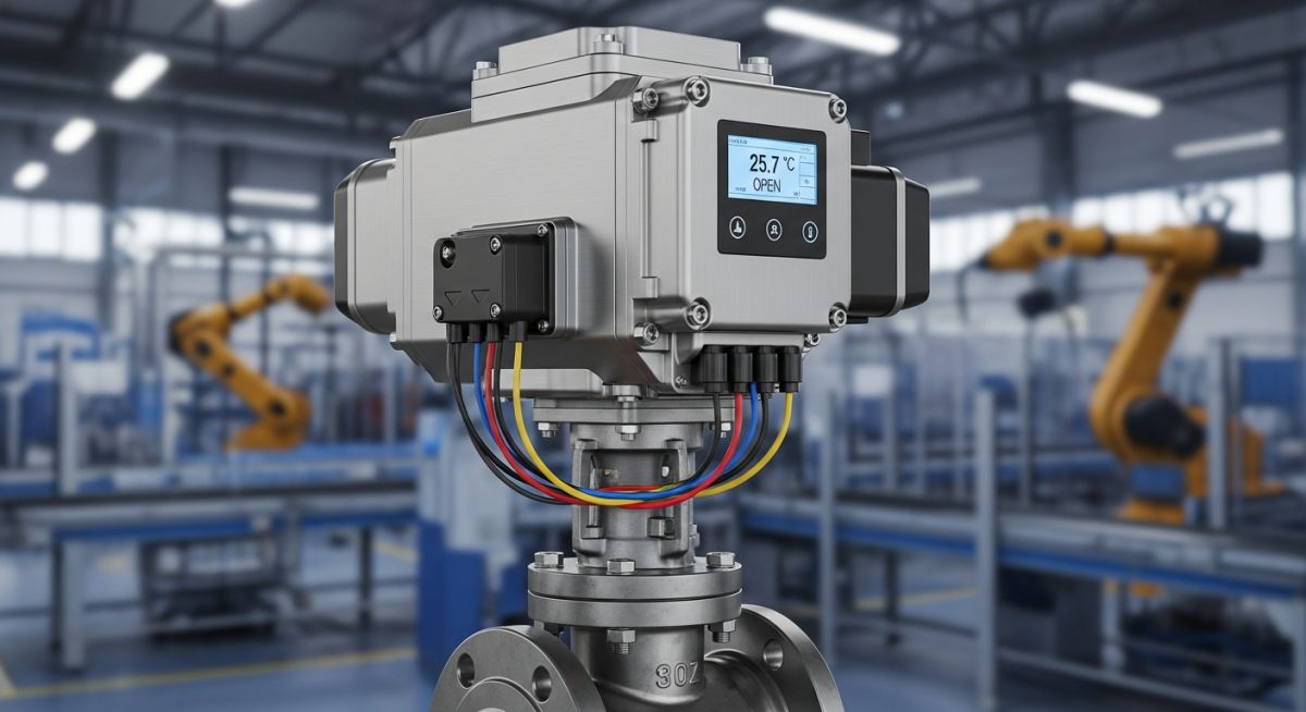
Learn what actuators are, their key parts, how they work, the different types (hydraulic, pneumatic, electric), and how to select them.

Master Process Control fundamentals, PID tuning, and feedback loops. Explore ASME/ISA standards for industrial automation and system stability in 2026.
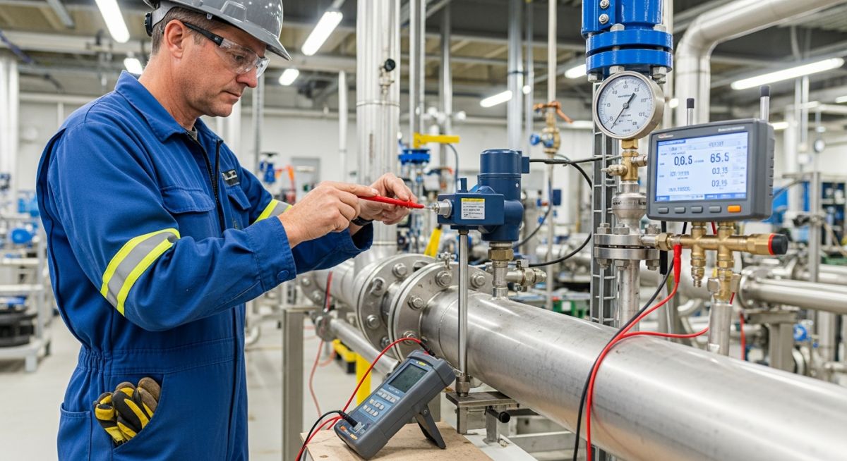
Master the fundamentals of Instrumentation Engineering. Explore core components, control loops, and industrial examples in this 2500+ word engineering guide.