Master the essential characteristics of crude oil including API gravity, sulfur content, and viscosity for refinery design and safety standards.

Master the essential characteristics of crude oil including API gravity, sulfur content, and viscosity for refinery design and safety standards.
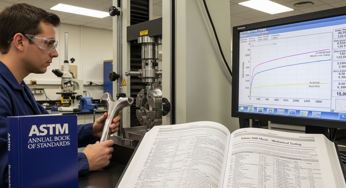
Master ASTM Standards in 2026. Explore development, the Annual Book of Steel, and a critical ASTM vs ASME comparison for global engineering compliance.
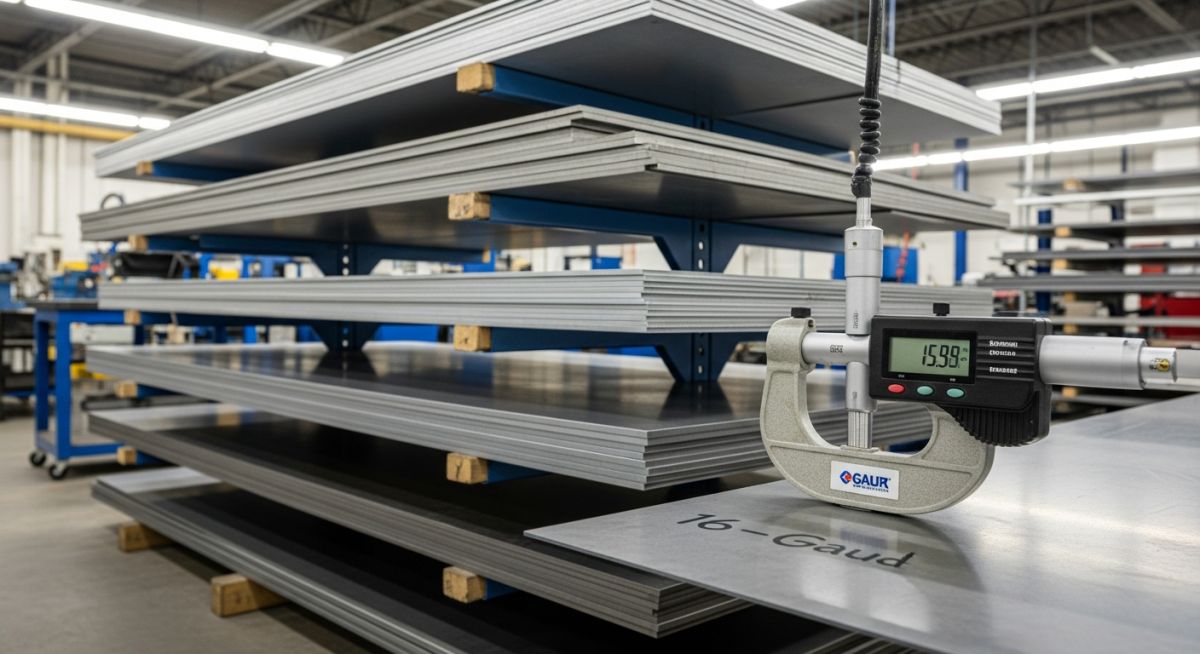
Access the definitive 2026 Sheet Metal Gauge Chart. Compare thickness for mild steel, aluminum, and stainless steel with decimal equivalents and ASTM standards.

The definitive guide to Through Bolting in construction and machinery. Learn the differences from anchor bolts, best practices for preload, and shear resistance standards.

Comprehensive engineering guide to ASTM A53 Pipe. Learn about Grade A vs B, chemical composition, Schedule 40 dimensions, and A53 vs A106 selection logic.

Master the various types of plumbing pipes for 2026. Compare copper, PEX, PVC, and CPVC with engineering standards, advantages, and applications.