Types of Piping Branch Fittings: A 2026 Guide to Tees, Olets, & Stubs
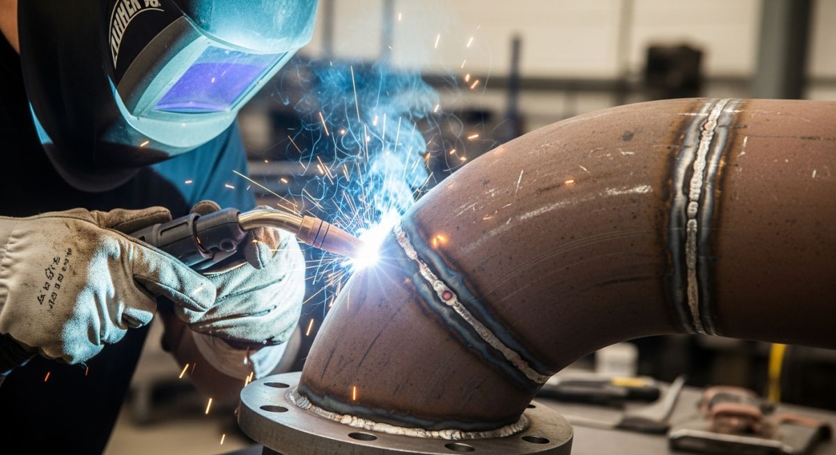
Figure 1: A Weldolet installation providing a reinforced branch connection on a high-pressure header.
In the complex geometry of a process plant, pipes rarely run in straight lines. They split, merge, and divert flow. The selection of the types of piping branch fittings is one of the most frequent decisions a Piping Engineer makes. Should you cut the pipe to install a standard B16.9 Tee, or drill a hole to weld on an Olet?
What are the Main Types of Branch Fittings?
Piping branch connections are generally categorized into three engineering methods, each governed by specific codes:
- Standard Tees (ASME B16.9): Manufactured butt-weld fittings offering the highest integrity and lowest Stress Intensification Factor (SIF).
- Integrally Reinforced Fittings (MSS SP-97): Commonly known as “Olets” (Weldolet, Sockolet, Threadolet). These are welded directly onto the run pipe (header) and provide self-reinforcement.
- Fabricated Connections (Stub-ins): A direct pipe-to-pipe weld, often requiring an additional “Repad” (Reinforcing Pad) to satisfy ASME B31.3 area replacement rules.
The choice depends on the Header-to-Branch Size Ratio, pressure class, and cyclic fatigue requirements. This guide breaks down the specifications, advantages, and limitations of each method.
Table of Contents
Quiz: Master of Branch Connections
Complete Course on
Piping Engineering
Check Now
Key Features
- 125+ Hours Content
- 500+ Recorded Lectures
- 20+ Years Exp.
- Lifetime Access
Coverage
- Codes & Standards
- Layouts & Design
- Material Eng.
- Stress Analysis
1. The 3 Main Methods of Branching
When designing a piping system, the engineer must balance pressure integrity, flow characteristics, and fabrication cost. Branch connections generally fall into three categories, ranging from the most robust (Tees) to the most economical (Stub-ins).
Butt Weld Tees (ASME B16.9)
The ASME B16.9 Tee is the gold standard for high-pressure and critical piping. It is a factory-manufactured fitting that requires cutting the header pipe completely.
- Equal Tee: Header and Branch are the same size.
- Reducing Tee: Branch is smaller than the Header.
❌ Cons: Requires 3 circumferential butt welds; cuts the line (cannot be installed on a live line).
Fabricated Stub-ins (Pipe-to-Pipe)
A “Stub-in” involves cutting a hole in the run pipe and welding the branch pipe directly to it. This creates a weak point where metal has been removed. To restore strength, a Reinforcing Pad (Repad) is often welded over the joint.
❌ Cons: Highest labor cost (complex cutting/fitting), poor fatigue resistance, high SIF.
2. The “Olet” Family: Integrally Reinforced Fittings
When you need a branch connection without cutting the entire header, you use an Integrally Reinforced Branch Connection, commonly known by the trade name “Olet.” These fittings are designed to MSS SP-97 standards and sit on top of the pipe, reinforcing the opening automatically.
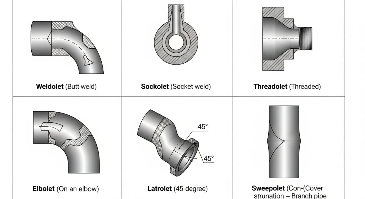
1. Weldolet®
Connection: Butt Weld (Beveled).
The most common Olet for branches 2 inches and larger. It provides a smooth flow transition and allows for a full penetration butt weld to the branch pipe.
2. Sockolet®
Connection: Socket Weld.
Used for Small Bore Connections (SBC), typically 2 inches and smaller. The branch pipe slides into the socket, making alignment easy, but creates a crevice risk.
3. Threadolet®
Connection: NPT / Threaded.
Similar to a Sockolet but used for low-pressure screwed piping systems. Common in utility air and water lines.
4. Latrolet®
Connection: 45° Angle.
Used when flow direction is critical (e.g., flare headers or relief lines) to reduce turbulence. It attaches at a 45-degree angle.
5. Elbolet®
Connection: Mounted on Elbow.
A space-saver. It is designed to be welded onto the curvature of a 90° Elbow or Return Bend, typically for thermowell installation.
6. Sweepolet®
Connection: Contoured Butt Weld.
The “Rolls Royce” of Olets. It has a long, contoured body that drastically reduces the Stress Intensification Factor (SIF). Used in high-fatigue pipelines.
3. Engineering Selection: Tee vs. Olet vs. Stub-in
The decision to use a Tee, an Olet, or a Stub-in is rarely random. It is driven by the Header-to-Branch Size Ratio, the pressure class, and the fabrication budget. The table below outlines the industry-standard selection criteria.
| Criteria | Butt Weld Tee (B16.9) | Weldolet (MSS SP-97) | Stub-in + Repad |
|---|---|---|---|
| Best Size Ratio | Size-on-Size (e.g., 10″ x 10″) | Reducing (e.g., 10″ x 2″) | Reducing (Low Pressure) |
| Cost (Material) | High | Medium | Low (Scrap Pipe) |
| Cost (Labor) | High (3 Welds + 2 Cuts) | Medium (1 Weld + 1 Cut) | High (Complex Fit-up) |
| Stress (SIF) | Lowest (Best for Fatigue) | Moderate | High (Poor for Fatigue) |
| NDE Capability | 100% Radiography (RT) | RT often difficult; UT/MT used | Visual / MT / PT only |
The “90-10” Rule of Thumb
- 👉 If Branch Size is > 70% of Header Size: Use a Standard Tee.
- 👉 If Branch Size is < 30% of Header Size: Use an Olet.
- 👉 Example: For a 10″ Header, use a Tee for 8″ or 10″ branches. Use a Weldolet for 2″ or 3″ branches. The middle ground (4″, 6″) is driven by cost analysis.
4. Reinforcement Calculations (ASME B31.3 Para 304.3.3)
When you cut a hole in a pipe to add a branch, you weaken the pressure containment capability of the header. The code requires you to prove that the metal removed has been compensated for by “surplus” metal in the vicinity of the opening. This is known as the Area Replacement Method.
// THE GOVERNING EQUATION
A1 + A2 + A3 + A4 ≥ Arequired
- Areq = d1 × th (Metal Removed)
- A1 = Surplus in Header Wall
- A2 = Surplus in Branch Wall
- A3 = Area of Fillet Welds
- A4 = Area of Repad (if needed)
The Concept: Most pipes are thicker than the absolute minimum required for pressure (due to corrosion allowance and mill tolerance). This “extra thickness” in the Header (A1) and the Branch (A2) often provides enough natural reinforcement.
If A1 + A2 + A3 is less than Arequired, the connection is weak. You must add an external Reinforcing Pad (Repad)—a steel plate welded over the branch—to provide the missing area (A4).
Note: Integrally reinforced fittings (Olets) are pre-calculated by the manufacturer (Bonney Forge, etc.) to meet these requirements automatically, provided the correct schedule is ordered.
Branch Connection Selector
Determine the optimal fitting (Tee, Olet, or Stub-in) based on size ratio and service conditions.
Weldolet®
Engineering Reason:
The Branch-to-Header ratio is small (< 30%). Using a Standard Tee would be wasteful and expensive. An integrally reinforced Weldolet provides sufficient strength and is easier to install.
Don’t miss this video related to Types of Piping Branch Fittings

Summary: Master Piping Engineering with our complete 125+ hour Certification Course: ……
5. O’let Deep Dive: Special Types & Features
Beyond the standard Weldolet and Sockolet, the MSS SP-97 family includes specialized fittings designed to reduce fabrication time and minimize leak paths in instrument connections.
Nipolet®
A combination of a Nipple + Olet. It is a one-piece manufactured fitting that provides a threaded or plain-end extension (typically 3.5″ to 6.5″ long).
✅ Best For: Installing vents, drains, and pressure gauges directly on headers without welding a separate pipe nipple.
Flangolet®
A combination of a Flange + Olet. The fitting sits on the pipe like an Olet but ends in a standard ASME B16.5 Flange face (Class 150 to 2500).
✅ Best For: Critical vessel or header connections where a flanged valve must be mounted as close to the run pipe as possible.
Brazolet®
Designed for use with Copper or Brass tubing (ASTM B61/B62). It provides a socket for silver brazing rather than welding.
✅ Best For: Medical gas lines, HVAC, and plumbing systems.
Couplet®
Essentially a Half-Coupling with a curved base tailored to the run pipe radius. It is designed for very high-pressure applications (Class 6000+).
✅ Best For: Hydraulic systems and high-pressure chemical injection points.
Key Engineering Feature: The Tapered Bore
Unlike a simple pipe-to-pipe stub-in, all Olets feature a funneled inlet (tapered bore). This design provides a smooth transition from the header to the branch, reducing turbulence and improving the “Burst Pressure” rating to equal that of the run pipe itself.
Advantages & Disadvantages of Using O’lets
Advantages
- Self-Reinforced: No need to calculate or fabricate separate Repads; the thickness is built-in.
- Material Savings: Uses significantly less metal than a full Tee, especially for large headers (e.g., 24″ x 2″).
- Flexible Installation: Can be installed on existing piping (Hot Tapping) without cutting the line apart.
- Inventory: A single 2″ Weldolet can often fit a range of header sizes (e.g., 6″ to 36″), reducing warehouse stock.
Disadvantages
- NDE Limitations: The complex geometry makes Radiography (RT) difficult or impossible for Sockolets/Threadolets.
- Stress Concentration: The sharp geometric transition creates a higher SIF than a Butt Weld Tee, creating fatigue risks.
- Weld Volume: Requires heavy filling of the “weld line” (groove), which can distort thin-wall headers (thermal distortion).
Comparison Table: Types of O’lets
| Olet Type | Connection Style | Typical Size Range | Primary Application |
|---|---|---|---|
| Weldolet | Butt Weld | 2″ to 24″+ | Standard branch connection for process piping (high pressure/temp). |
| Sockolet | Socket Weld | 1/2″ to 2″ | Small Bore Connections (SBC) for drains, vents, and instruments. |
| Threadolet | Threaded (NPT) | 1/2″ to 2″ | Low-pressure utility lines (Air, Water) or screwed piping specs. |
| Nipolet | Plain / Threaded | 1/2″ to 2″ | Vents and drains requiring immediate valve mounting (one weld only). |
| Latrolet | 45° Angle | Various | Relief headers and flare lines to minimize flow turbulence. |
Case Study: Small Bore Fatigue Failure
The Scenario: On a newly commissioned Reciprocating Compressor discharge line (12-inch, Class 600), a standard 3/4″ Sockolet was installed for a pressure transmitter connection. The line experienced significant high-frequency vibration during operation.
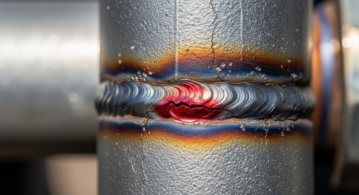
Why Did It Fail?
After only 3 weeks of operation, a gas leak was detected. The root cause analysis revealed:
- 1. High SIF: Standard Sockolets have a high Stress Intensification Factor (SIF ~ 2.0 to 2.5) due to the sharp geometric transition at the fillet weld.
- 2. Unsupported Mass: The heavy pressure transmitter mounted on the small pipe created a “cantilever effect,” amplifying the vibration moment at the weld connection.
Operational Impact
Unplanned Shutdown
48 Hours
Required to depressurize and repair.
Revenue Loss
$1.2 Million
Production deferment.
The Correct Engineering Solution
The failed Sockolet was replaced with a Sweepolet®.
- Lower SIF: The Sweepolet’s contoured body reduced the stress concentration (SIF ~ 1.1).
- Butt Weld: Replaced the fillet weld with a radiographable butt weld for higher fatigue resistance.
- Bracing: A 2-plane bracing clamp was installed to secure the transmitter, eliminating the cantilever moment.
Frequently Asked Questions (FAQ)
What is the difference between a Stub-in and a Stub-on?
The difference lies in how the branch pipe sits relative to the header. In a Stub-in (Set-in), the hole is cut to the branch OD, and the branch pipe is inserted until it is flush with the header’s inner diameter. This offers better strength but requires precise profiling. In a Stub-on (Set-on), the branch sits on top of the header OD. Stub-ons are easier to fabricate but structurally weaker.
When should I use a Latrolet (45°) instead of a standard 90° fitting?
Lateral connections (45°) are used when flow dynamics are critical. They are standard in Relief/Flare Headers to minimize backpressure and turbulence when merging flows. They are also used in drainage systems (gravity flow) and piggable lines to facilitate the smooth passage of cleaning pigs.
Can I perform Radiography (RT) on an Olet connection?
It depends on the type. A Weldolet creates a Butt Weld, which can be radiographed, although the changing geometry makes interpretation difficult (Ultrasonic Testing is often preferred). Sockolets and Threadolets use fillet welds, which cannot be radiographed; they are inspected using Magnetic Particle (MT) or Dye Penetrant (PT) only.
What is the “Run Pipe” vs. “Branch Pipe”?
The “Run Pipe” (or Header) is the main pipe carrying the primary flow. The “Branch Pipe” is the smaller (or equal) line diverting from it. In dimension specifications (e.g., 10″ x 4″), the first number (10″) is always the Run/Header, and the second (4″) is the Branch.
Conclusion: Making the Right Connection
Choosing among the various types of piping branch fittings is more than just a matter of cost—it determines the mechanical integrity and life-cycle of your plant.
Whether you opt for the robustness of a Butt Weld Tee for critical headers, or the efficiency of a Weldolet for reducing branches, always adhere to the “90-10 Rule” and verify your reinforcement calculations per ASME B31.3. A cheap connection today is an expensive leak tomorrow.
📚 Recommended Resources: Types of Piping Branch Fittings
Read these Guides


Related posts:
![High-grade industrial Wing Nut Types and Applications for mechanical assemblies.]()
Wing Nut Types and Applications: The 2026 Engineering Guide
![Industrial Monorail Crane Systems installed in a modern manufacturing plant 2026.]()
Monorail Crane Systems: Design, Types & 2026 Standards Guide
![Lead engineer performing a Factory Acceptance Test FAT on an industrial skid system 2026]()
Factory Acceptance Test FAT: The 2026 Engineering Guide to Zero-Defect Delivery
![Professional engineering workspace showing a Basis of Design document layout for a 2026 project.]()
Basis of Design: How to Write a BOD for Engineering Projects in 2026
![Industrial Flare Knockout Drum Sizing and installation in a refinery relief system.]()
Flare Knockout Drum Sizing: Design & API 521 Standards (2026 Guide)
![Advanced Reboiler Control Systems in a modern petrochemical refinery 2026.]()
Reboiler Control Systems: Engineering Guide to Precision Control 2026


