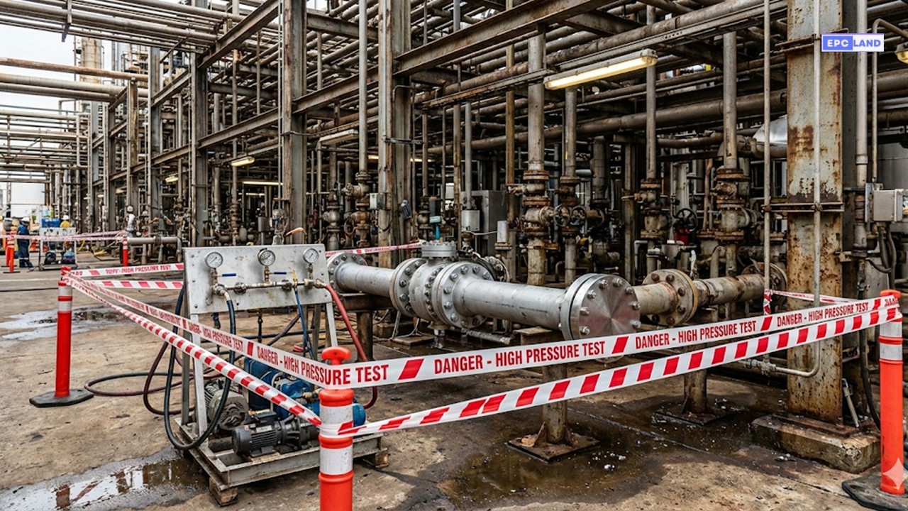
✅ Verified for 2026 by Epcland Engineering Team Piping Hydrostatic Test Procedure (ASME B31.3): Field Guide 2026 The Piping Hydrostatic Test Procedure (ASME B31.3) is the mandatory final quality gate for process piping systems in refineries and chemical plants. Unlike cross-country pipelines, process piping networks are complex, involving mixed metallurgies (Carbon Steel, Stainless Steel), high-pressure fittings, and critical tie-ins to live units. This guide breaks down the rigorous ASME B31.3 requirements, specifically addressing the 1.5x test pressure standard and the nuances of testing in a brownfield environment. Code Definition: ASME B31.3 Section 345 The standard requires that all new piping systems be leak tested to ensure tightness and structural integrity. A hydrostatic leak test is preferred, conducted at a pressure of not less than 1.5 times the Design Pressure (corrected for temperature), held for a sufficient time to examine all joints. ⚡ Quick Navigation 1 ASME B31.3 Code Requirements & Formulas 2 Preparation: Checklists & Water Quality (Cl-) 3 Case Study: Brownfield Refinery Upgrade 4 FAQ & Reinstatement 🧪 QC Inspector Knowledge Check Question 1 of 5 1. Per ASME B31.3, what is the standard minimum hydrostatic test pressure multiplier for process piping? A. 1.1 times Design Pressure B. 1.25 times Design Pressure C. 1.5 times Design Pressure 2. When hydrotesting Austenitic Stainless Steel (e.g., 304/316), what is the critical water quality parameter? A. pH Level > 9.0 B. Chloride Content (typically < 50 ppm) C. Turbidity < 10 NTU 3. According to ASME B31.3, how long must the test pressure be held? A. Minimum 24 Hours B. Minimum 10 mins (or time to inspect all joints) C. Minimum 4 Hours 4. Why must high-point vents be open during filling? A. To displace trapped air B. To cool the water C. To filter particulates 5. What is the acceptable range for pressure gauge calibration? A. 0 to 100% of Test Pressure B. 1.5 to 4 times the Test Pressure C. Exactly equal to Test Pressure Previous Next Question Figure 1: Typical Hydrotest Setup in a Live Refinery Unit (Brownfield). Engineering Theory & ASME B31.3 Compliance The Piping Hydrostatic Test Procedure (ASME B31.3) is distinct from pipeline testing (ASME B31.4/8). While pipelines focus on long-distance hoop stress, process piping inside facilities deals with complex geometries, flanges, valves, and varying design temperatures. The code explicitly states that the test pressure must create a stress state in the piping material that exceeds its operating conditions to verify safety factors. One common point of confusion is Pneumatic vs hydrostatic testing piping. Hydrostatic testing (using water) is the standard default because water is virtually incompressible. In the event of a rupture, the stored energy release is minimal compared to compressed gas (pneumatic), which expands explosively. Pneumatic testing is permitted only when the piping structure cannot support the weight of water or if traces of water are detrimental to the process (e.g., acid lines), and it requires vastly stricter safety exclusion zones. Figure 2: Test Loop Diagram showing High Point Vents, Low Point Drains, and the Calculation Formula. ASME B31.3 Test Pressure Calculation To perform a compliant ASME B31.3 test pressure calculation, engineers must account for the difference between the testing temperature (ambient) and the design temperature (operating). Strength properties of steel degrade as temperature rises; therefore, the test pressure at ambient conditions must be increased to simulate the stress at the hotter design temperature. The Golden Formula (Section 345.4.2) PT = 1.5 × PD × (ST / SD) Where: PT = Minimum Test Pressure (Gauge) PD = Internal Design Pressure ST = Allowable Stress at Test Temperature (Ambient) SD = Allowable Stress at Design Temperature Constraint: The value of (ST / SD) shall not exceed 6.5. Additionally, ensure PT does not generate stress exceeding the Yield Strength of the pipe material at test temperature. Manifold & Gauge Requirements The Hydrotest manifold design pressure must exceed the maximum test pressure of the system by a safety margin (typically 1.2x). The manifold connects the pump to the system and usually houses the primary pressure gauge and relief valve. Gauge Range: Gauges must be calibrated and have a range between 1.5 and 4.0 times the test pressure. Ideally, the needle should point to the middle third of the dial (12 o'clock position). Calibration: Certificates must be valid (usually within 6 months) and traceable to NIST or national standards. Positioning: At least two gauges are required: one at the pump (discharge) and one at the highest point or furthest extremity of the loop. Comparison of ASME B31.3 Leak Testing Methods Test Method Test Medium Pressure Factor (Min) Primary Risk / Note Hydrostatic Potable Water 1.5 x Design Pressure Freezing, Weight of water Pneumatic Air / Nitrogen 1.1 x Design Pressure Explosive Energy Storage Initial Service Process Fluid Operating Pressure Cat D fluid only (Non-hazardous) Sensitive Leak Gas + Bubble Solution 1.25 x Design Pressure OR 15 psig Used for very small leaks *Note: Pneumatic testing requires a specialized "Gas Test Procedure" and extensive safety radii calculations. Case Study: Piping Hydrostatic Test Procedure (ASME B31.3) in Live Refinery Project: Diesel Hydrotreater (DHT) Unit Revamp - Loop #402 Figure 3: Quality Control check verifying water chloride levels are below 50 ppm before filling 304SS piping. 📋 Technical Specifications Piping Spec: 6" A312 TP304 (Stainless) & A106 Gr.B (CS) Design Pressure: 25 Bar (at 180°C) Test Pressure: 41.5 Bar (Corrected for Temp) Environment: Brownfield (Live Unit) The Challenge: Metallurgy & Contamination The revamp project involved replacing a corroded Carbon Steel (CS) header with a new Stainless Steel (304SS) loop connected to existing equipment. The primary engineering challenge was the strict water quality requirement. While standard industrial water is acceptable for Carbon Steel, using it on Austenitic Stainless Steel can be catastrophic. The Risk: High chloride levels (>50 ppm) in the test water can remain in crevices (like socket welds or flange gaps) after draining. Upon startup, as the system heats up, the water evaporates, concentrating the chlorides and causing Chloride Stress Corrosion Cracking (CSCC), which can lead to sudden brittle failure weeks later. Execution: Package Prep & Water Quality The Field Engineer initiated the process using a strict Hydrotest package preparation checklist. This document verified that all "Sensitive Equipment" (Control Valves, Flow Transmitters) were removed or spaded off to prevent damage from the high test pressure. To address the metallurgy risk, the team sourced Demineralized Water (DM Water) via a tanker truck. Critical Control Point: Chloride Limits The QA/QC Manager tested the Water chloride content for stainless steel using a titration kit. The result was 15 ppm, well below the 50 ppm limit typically mandated by ASME B31.3 guidelines and client specifications (e.g., Shell DEP or PIP). Only then was filling authorized. Result & Reinstatement The system was pressurized to 41.5 Bar and held for 30 minutes. The inspector walked the line, checking all flange faces and welds. No leaks were observed, and the pressure recorder showed a flat line. After the test was signed off, the team began Post-hydrotest reinstatement activities. This is the most dangerous phase for future leaks if done poorly. The temporary spades were removed, and new gaskets were installed at every flange broken for the test. The line was blown dry with oil-free compressed air to remove residual moisture, ensuring the stainless steel was dry before the introduction of hydrocarbons. Project Outcome The loop was successfully commissioned with zero leaks. The use of DM water prevented any initial corrosion sites, validating the rigorous adherence to the ASME B31.3 mixed-metallurgy protocols. Frequently Asked Questions What should be included in a Hydrotest package preparation checklist? A comprehensive Hydrotest package preparation checklist is the roadmap for the test. It must include marked-up P&IDs (highlighting the test limits), isometric drawings, the blind list (spade locations), the valve isolation list, calibration certificates for gauges and relief valves, and the specific test pressure calculation sheet approved by the process engineer. When should I choose Pneumatic vs hydrostatic testing for piping? The choice of Pneumatic vs hydrostatic testing piping comes down to safety and process requirements. Hydrostatic is always the first choice due to safety. Pneumatic (Air/N2) is only used if the piping structure cannot support the weight of water (e.g., large diameter gas flares) or if the presence of moisture is strictly prohibited (e.g., cryogenic service or acid lines). Pneumatic tests require significantly larger exclusion zones. What determines the Hydrotest manifold design pressure? The Hydrotest manifold design pressure should be rated higher than the highest test pressure it will ever encounter. Typically, manifolds are built to ASME B31.3 high-pressure specs (e.g., Class 2500 fittings) to ensure they are universal tools. The manifold's Relief Valve (PSV) must be set at exactly the test pressure plus a small margin (e.g., +5% or +10%) to prevent over-pressurization of the system. What are critical Post-hydrotest reinstatement activities? Post-hydrotest reinstatement activities ensure the line is ready for service. This includes: draining and drying (air blowing or swabbing), removing all temporary spades/blinds, reinstalling control valves and sensitive instruments, installing new gaskets at all flanged joints broken during the test, and torquing bolts to spec. Failure to replace gaskets is a leading cause of startup leaks. Final Engineering Note The Piping Hydrostatic Test Procedure (ASME B31.3) is more than just pumping water; it is a calculated validation of engineering design and construction quality. Whether testing a single spool or a massive refinery unit, strict adherence to pressure calculations, chloride limits, and safety buffers ensures the asset operates safely for decades. Download 2026 Hydrotest Package Checklist (PDF)