Real-World ASME B31.3 Field Re-Route: A Case Study in Urgent Plant Upgrades
In the fast-paced world of EPC (Engineering, Procurement, and Construction) projects, especially urgent plant upgrades, encountering unforeseen challenges is a common occurrence. Among the most frustrating and potentially project-derailing issues are inaccuracies in existing as-built drawings. These discrepancies can halt progress, inflate costs, and, critically, compromise compliance with vital codes like ASME B31.3. This article dives into a real-world scenario where a critical ASME B31.3 field re-route became necessary, demonstrating how practical application of code knowledge, rather than just theoretical understanding, can save a project from significant delays and ensure continued safety and operational integrity.
Table of Contents
- The Hidden Dangers of Inaccurate As-Built Drawings in EPC Projects
- Navigating Field Challenges with ASME B31.3: A Practical Approach
- Key ASME B31.3 Sections for Field Modifications
- Tools and Techniques for Rapid Field Assessment and Redesign
- Ensuring Compliance and Mitigating Risk in Dynamic Environments
- Documentation Best Practices for Field Changes
- The Role of Collaboration Between Disciplines
- Conclusion & Key Takeaways
- Further Learning & Resources
- Frequently Asked Questions (FAQ)
The Hidden Dangers of Inaccurate As-Built Drawings in EPC Projects
As-built drawings are supposed to be the definitive record of a completed project, reflecting all field changes and actual installed conditions. However, in the real world, they often fall short, becoming a silent saboteur of future modifications and upgrades.
Why As-Built Discrepancies Are More Common Than You Think
The reasons for inaccurate as-builts are manifold:
- Project Pace: In fast-tracked projects, there’s often insufficient time allocated for diligent as-built documentation.
- Field Changes Not Recorded: Minor (and sometimes major) modifications made during construction might not be formally captured and transferred to the design team for drawing updates.
- Lack of Tools: Historically, manual measurement and drafting made perfect accuracy challenging. While modern tools exist, their adoption isn’t universal.
- Ownership Ambiguity: Confusion over who is ultimately responsible for updating and verifying as-builts can lead to oversight.
- Legacy Systems: Older plants might have as-builts based on outdated technologies or even hand-drawn sketches, making them inherently less precise.
The Costly Consequences: Delays, Rework, and Safety Risks
The impact of flawed as-builts can be severe:
- Project Delays: Discovering clashes or interferences on-site during a new installation forces immediate re-design, delaying critical path activities.
- Rework and Cost Overruns: Pipes fabricated off-site based on incorrect data will need costly field modifications or even complete re-fabrication.
- Safety Hazards: Misinformation about existing conditions can lead to hazardous situations during hot work, tie-ins, or equipment placement, potentially compromising personnel safety and plant integrity.
- Operational Inefficiencies: Inaccurate documentation hinders effective maintenance, troubleshooting, and future operational planning.
| Discrepancy Type | Planned Scenario (Based on Design) | Actual Scenario (Based on Inaccurate As-Built) | Potential Impact |
|---|---|---|---|
| Pipe Routing/Elevation | Clearance of 150mm from structural beam. | Pipe clashes directly with structural beam. | Reroute required, fabrication rework, project delay, increased cost. |
| Support Location/Type | Design calls for a standard pipe shoe support at specific location. | Existing structure prevents support installation; existing pipe is actually clamped elsewhere. | New support design needed, potential stress issues if not addressed, constructability challenges. |
| Nozzle Orientation | Equipment nozzle oriented vertically for direct pipe connection. | Actual nozzle rotated 45 degrees horizontally. | Spool piece rework, potential stress on connected equipment, difficult connection. |
| Valve Accessibility | Valve located for easy operation and maintenance access. | Valve stem is now too close to a wall or another pipe run. | Compromised operation, safety hazard, potential need for valve re-location. |
| Material Specification | Existing pipe documented as Carbon Steel. | Field inspection reveals Stainless Steel or an unknown alloy. | Welding procedure issues, material incompatibility, potential for galvanic corrosion, code violation. |
Navigating Field Challenges with ASME B31.3: A Practical Approach
When discrepancies arise, especially on critical, time-sensitive projects, a deep practical understanding of ASME B31.3 becomes invaluable. It’s not just about knowing the rules but understanding how to apply them flexibly and judiciously to find compliant solutions under pressure.
Pro-Tip From The Field
On an urgent plant upgrade project, the as-built drawings for an existing piping tie-in proved inaccurate; a crucial support beam was precisely where the new pipe run was designed to go. Without halting the entire construction, we quickly re-routed the pipe, using ASME B31.3’s flexibility analysis and support span tables to confirm the new configuration could withstand operating loads and avoid excessive stress concentrations. This allowed us to maintain code compliance and meet the tight installation deadline, preventing significant project delays.
Key ASME B31.3 Sections for Field Modifications
When faced with a field re-route or modification, several sections of ASME B31.3 become critical:
- Chapter II, Part 2 – Design Conditions and Criteria (e.g., Pressure Design, Section 304): While the original design conditions remain, any significant re-route might alter factors like static head or introduce new pressure surges that need consideration.
- Chapter II, Part 5 – Flexibility and Support (Section 319 & 321): This is paramount. A re-route changes the geometry, affecting flexibility. You must ensure the new configuration can accommodate thermal expansion and contraction without overstressing the pipe or connected equipment. Section 319 details methods for flexibility analysis, and Section 321 covers support design.
- Chapter II, Part 3 – Design for Sustained and Occasional Loads (Section 302.3): Field re-routes must still consider sustained loads (weight, pressure) and occasional loads (wind, seismic, water hammer).
- Chapter III – Materials (Section 323): If any new material is introduced or existing material is re-used, its suitability for the service and compliance with code requirements must be verified.
- Chapter V – Fabrication, Assembly, and Erection (Section 328): Welding procedures, bending, and assembly practices must adhere to the code, even for rapid field work.
Tools and Techniques for Rapid Field Assessment and Redesign
Time is of the essence during field modifications. Engineers need efficient tools and techniques:
- Laser Scanners and 3D Modeling: For complex areas, laser scanning can quickly capture accurate as-built conditions, feeding directly into 3D modeling software for rapid clash detection and re-design.
- Portable Pipe Stress Analysis Software: While full-blown FEA might be overkill for a simple re-route, portable versions or cloud-based tools can provide quick stress and flexibility checks.
- Field Measurement Tools: Digital inclinometers, laser distance meters, and even traditional tape measures, wielded by experienced personnel, are indispensable.
- Standard Piping Details: Having a library of pre-approved standard details for supports, hangers, and small bore connections can accelerate design.
- Experienced Eyes: Nothing replaces the practical experience of a seasoned piping or stress engineer who can quickly eyeball a re-route and identify potential issues.
Ensuring Compliance and Mitigating Risk in Dynamic Environments
Maintaining ASME B31.3 compliance during dynamic field changes involves:
- Risk Assessment: Before any modification, quickly assess the potential risks associated with the change – both operational and safety-related.
- Design Basis Adherence: Ensure that the re-routed piping still meets the original design basis for pressure, temperature, and fluid properties.
- Stress Concentration Avoidance: Pay close attention to fittings, branch connections, and transitions to avoid introducing new stress concentrations.
- Support Optimization: Ensure new support locations are adequate and existing supports are not overstressed or rendered ineffective.
- Material Traceability: Always maintain traceability of materials used, even for small field additions.
Documentation Best Practices for Field Changes
The urgency of field changes should never compromise documentation:
- Field Sketches with Dimensions: Clear, dimensioned sketches are crucial for immediate record-keeping.
- Photographic Evidence: Before and after photos provide invaluable visual records.
- Change Control Log: Maintain a log of all field changes, including the reason for the change, the solution implemented, and the individuals involved.
- As-Built Updates: Ensure that all field changes are meticulously incorporated into the final as-built drawings and relevant project documentation.
- Formal Approvals: Even if initial decisions are made in the field, ensure formal review and approval by the relevant engineering disciplines (piping, stress, civil/structural, operations) as soon as practically possible.
The Role of Collaboration Between Disciplines (Piping, Stress, Construction)
Successful navigation of field re-routes hinges on effective collaboration:
- Piping Engineers: Identify the clash, propose initial re-route concepts, and prepare field sketches.
- Stress Engineers: Quickly analyze the proposed re-route for flexibility, support loads, and stress compliance with ASME B31.3. Provide immediate feedback on feasible options.
- Construction Managers/Supervisors: Provide constructability input, assess impact on schedule, and execute the physical work. Their practical insight is invaluable.
- Materials Specialists: Advise on material compatibility and availability for any new sections.
- Operations/Maintenance: Offer insights into accessibility, future maintenance, and operational impacts of the re-route.
Master Piping Engineering with EPCLAND’s Complete Course, designed for real-world success.
Conclusion & Key Takeaways
The case of the ASME B31.3 field re-route due to inaccurate as-built drawings vividly illustrates a common challenge in EPC projects. It underscores that while theoretical knowledge of piping codes is foundational, the true value lies in the practical application of this knowledge to solve unforeseen problems under pressure. Mastering ASME B31.3’s flexibility analysis, support design principles, and material requirements is not merely academic; it’s essential for ensuring project success, maintaining compliance, and, most importantly, safeguarding plant integrity and personnel safety.
Professionals who can quickly assess, analyze, and implement compliant field modifications, leveraging code knowledge and collaborative efforts, are indispensable in today’s dynamic project environments. Continually developing these problem-solving skills, rooted deeply in code understanding, is a career imperative for every piping professional.
Further Learning & Resources
- ASME B31.3 Process Piping Code Complete Course
- Pipe Stress Analysis Using Caesar II (Basic to Advance)
- Piping Layouts and Design Concepts
Frequently Asked Questions (FAQ)
What is an “as-built drawing” in piping engineering?
An as-built drawing is a revised set of drawings submitted by a contractor upon completion of a project. It reflects all changes made to the original design during construction, showing the exact dimensions, geometry, and location of all installed components, including piping, equipment, and structures, as they were actually built in the field.
Why are inaccurate as-built drawings a problem in plant upgrade projects?
Inaccurate as-built drawings can lead to significant problems, including clashes (where new components interfere with existing ones), rework due to incorrect fabrication, costly project delays, increased safety risks, and difficulty in future maintenance or modifications, as the actual plant configuration deviates from the documented one.
How does ASME B31.3 address field modifications?
ASME B31.3, while primarily a design code, applies to the fabrication, installation, and testing of process piping. For field modifications, relevant sections such as those on flexibility analysis (Section 319), support design (Section 321), and material requirements (Section 323) must still be adhered to. Any changes must ensure the modified system continues to meet the code’s requirements for pressure, temperature, and stress limits.
What is the role of flexibility analysis in a piping field re-route?
Flexibility analysis is critical in a piping field re-route to ensure that the new pipe configuration can safely accommodate thermal expansion and contraction without generating excessive stresses on the pipe itself or undue forces on connected equipment and supports. A re-route changes the stiffness and thermal expansion characteristics, making a re-assessment essential for ASME B31.3 compliance.
Who should be involved in making decisions for an urgent ASME B31.3 field re-route?
For an urgent ASME B31.3 field re-route, effective collaboration is crucial. Key personnel should include a Piping Designer/Engineer (for layout and routing), a Stress Engineer (for flexibility and support analysis), a Construction Manager/Supervisor (for constructability and schedule impact), and potentially a Materials Specialist (for material verification and compatibility). Rapid communication and joint decision-making are vital.
Related posts:
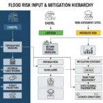
![Technical infographic showing the workflow of flood risk assessment for data centres, including hydrological inputs and mitigation strategies.]()
Flood Risk Assessment for Data Centres: Engineering Design Guide
![Isometric engineering rendering of a data centre campus featuring flood protection barriers and elevated utility infrastructure for disaster resilience.]()
Flood Protection Level Selection for Mission-Critical Data Centre Infrastructure
![Cross-section diagram of a data centre foundation showing soil strata, pile foundations, and groundwater monitoring wells for geotechnical analysis.]()
Geotechnical Requirements for Data Centres: A Structural Engineering Guide
![Civil 3D interface showing a 3D site grading model with color-coded cut and fill zones for earthwork optimization.]()
Optimizing Cut and Fill Operations Using Civil 3D and GIS
![3D digital terrain model showing site grading, flood protection levels, and cut-fill zones for industrial infrastructure development.]()
Establishing FPL and Estimating Cut Fill Quantities for Site Grading
![3D engineering model showing cut and fill optimization for industrial site grading and earthwork balancing.]()
Cut and Fill Optimization: 8 Engineering Studies for Site Grading