What is Socket Welding? The Ultimate Guide to Socket Weld Pipe Fittings

Imagine this: You are on-site during a high-pressure hydrotest when a small-bore bypass line suddenly develops a pinhole leak. The cause? A common but fatal error in the assembly of Socket Weld Pipe Fittings. Despite their small size, these components are the backbone of small-bore piping in refineries and power plants. If you do not understand the mandatory 1.6mm expansion gap or the nuances of ASME B16.11, you are looking at a ticking time bomb of fatigue failure or crevice corrosion. This guide breaks down everything an engineer needs to know to master these critical connections.
Key Takeaways
- Socket Weld Pipe Fittings are designed for small-bore piping (usually NPS 2 and smaller) and provide superior leak integrity compared to threaded joints.
- ASME B31.3 requires a 1.6mm (1/16 inch) expansion gap before welding to prevent axial stress and cracking during cooling.
- While strong in high-pressure applications, these fittings are susceptible to crevice corrosion and are generally avoided in radioactive or highly corrosive services.
Featured Snippet: What are Socket Weld Pipe Fittings?
Socket Weld Pipe Fittings are high-pressure piping components where the pipe is inserted into a recessed area (socket) of a fitting before being joined by a single fillet weld. Governed by ASME B16.11, they are primarily used for small-bore piping (NPS 2 and below) to ensure leak-proof, high-integrity permanent joints in industrial fluid systems.
Founder’s Insight
“In my 20 years of piping design, I have seen more failures in Socket Weld Pipe Fittings due to poor ‘gap’ management than almost any other cause. Never underestimate the importance of that 1.6mm space—it is the difference between a system that lasts decades and one that fails in weeks due to thermal fatigue.”
— Atul Singla, Founder of Epcland
Table of Contents
- What is a Socket Weld?
- Technical Working of Socket Weld Pipe Fittings
- Essential Types of Socket Weld Pipe Fittings
- Design Features of High-Pressure Fittings
- Engineering Advantages
- Critical Drawbacks and Risks
- Socket Weld vs Butt Weld Fittings
- Installation Best Practices
- Socket Weld Failure Case Study
- Expert Insights & Field Lessons
Complete Course on
Piping Engineering
Check Now
Key Features
- 125+ Hours Content
- 500+ Recorded Lectures
- 20+ Years Exp.
- Lifetime Access
Coverage
- Codes & Standards
- Layouts & Design
- Material Eng.
- Stress Analysis
Engineering Challenge: Socket Weld Mastery
Test your knowledge on ASME B16.11 standards and installation protocols.
Question 1 of 5
Which ASME standard specifically covers forged Socket Weld Pipe Fittings?
What is a Socket Weld?
A Socket Weld is a piping connection detail in which a pipe is inserted into a recessed area of a fitting, valve, or flange. Unlike butt weld fittings, which require the pipe ends to be beveled and joined end-to-end, Socket Weld Pipe Fittings utilize a "female" socket geometry to house the "male" pipe end. The structural integrity of the joint is provided by a single circumferential fillet weld applied at the intersection of the pipe exterior and the face of the fitting.
Governed by the ASME B16.11 standard, these fittings are the industry standard for small-bore piping systems—typically defined as pipes with a Nominal Pipe Size (NPS) of 2 inches or smaller. Because the pipe sits inside the socket, alignment is inherently easier than with butt welding, making it a preferred choice for rapid field installation in high-pressure hydraulic and steam lines.

Technical Working of Socket Weld Pipe Fittings
The mechanical reliability of Socket Weld Pipe Fittings depends entirely on a precise installation sequence. The process begins with the square-cutting of the pipe. Unlike butt welding, no complex beveling is required, but the pipe end must be deburred and cleaned to ensure a smooth fit within the socket.
The 5-Step Installation Protocol
- Cleaning: Remove all oil, grease, and oxide scales from both the pipe end and the fitting socket to prevent weld porosity.
- Insertion & Bottoming: Insert the pipe into the fitting until it firmly contacts the internal shoulder (the "bottom").
- The 1.6mm Withdrawal: This is the most critical step. The pipe must be withdrawn approximately 1.6mm (1/16 inch) from the bottomed position. This creates an expansion gap.
- Tack Welding: Secure the pipe in the withdrawn position with 2-4 small tack welds to maintain the gap during the final pass.
- Fillet Welding: Apply the final fillet weld. The leg length of the weld must be at least 1.09 times the nominal wall thickness of the pipe to meet ASME B31.3 safety factors.
Essential Types of Socket Weld Pipe Fittings (ASME B16.11)
The ASME B16.11 standard covers various geometries designed to redirect, branch, or terminate fluid flow. Because these are forged components, they offer superior grain structure and strength compared to cast alternatives. The most common types include:
- Socket Weld Elbows (90° and 45°): Used to change the direction of the piping run.
- Socket Weld Tees: Available in Equal or Reducing patterns to create 90-degree branches.
- Full and Half Couplings: Used for joining two pipes or for vessel nozzle connections.
- Socket Weld Unions: A three-piece fitting that allows for easy disassembly of the piping system for maintenance.
- Caps and Crosses: Used for sealing the end of a line or creating four-way intersections.
- Reducers and Inserts: Components designed to transition between different pipe diameters within the socket system.
Design Features of High-Pressure Socket Weld Fittings
Engineers specify Socket Weld Pipe Fittings based on "Pressure Classes"—typically Class 3000, 6000, and 9000. These classes do not represent the exact PSI rating but rather correlate with the schedule of the pipe being used. For instance, a Class 3000 fitting is generally matched with Schedule 80 pipe.
Key design features include the Bore Diameter, which must be precisely machined to match the pipe's Outer Diameter (OD) with a specific tolerance to allow for fit-up without excessive play. The material of construction is usually ASTM A105 (Carbon Steel), ASTM A182 (Stainless Steel/Alloy Steel), or ASTM A350 (Low-Temperature Carbon Steel), ensuring the fitting can withstand the thermal and mechanical stresses of industrial service.
Engineering Advantages of Socket Weld Pipe Fittings
The widespread adoption of Socket Weld Pipe Fittings in high-pressure steam and chemical processing is not accidental. Their primary advantage lies in mechanical alignment. Because the pipe is seated within the socket, the fitting acts as its own alignment tool, eliminating the need for complex external clamps or "tack-and-check" procedures common in butt welding. This significantly reduces labor hours, especially in tight, congested pipe racks where maneuvering heavy equipment is impossible.
Furthermore, Socket Weld Pipe Fittings offer superior leak integrity. Unlike threaded connections, which rely on compound tapes or sealants and are prone to "weeping" under vibration, a fillet-welded socket joint is a permanent, hermetically sealed connection. From a fabrication standpoint, the lack of a need for pipe-end beveling (V-prep) saves significant preparation time. For small-bore lines (NPS 2 and under), these fittings provide the optimal balance between structural strength and installation speed.
Critical Drawbacks and Risks of Socket Weld Pipe Fittings
Despite their utility, Socket Weld Pipe Fittings are strictly prohibited in several high-risk industrial applications. The most glaring issue is Crevice Corrosion. The inherent 1.6mm gap between the pipe end and the socket shoulder creates a stagnant "dead zone" where corrosive media or moisture can accumulate. Over time, this localized environment becomes significantly more aggressive than the bulk fluid, leading to rapid wall thinning and unpredictable failure.
Another major concern is Radiographic Inspection (RT). While a butt weld can be easily X-rayed to find internal defects, the overlapping geometry of a socket weld makes RT interpretation extremely difficult and often inconclusive. Consequently, quality control usually relies on Magnetic Particle (MT) or Dye Penetrant (PT) testing, which only detects surface-level flaws. Furthermore, if the mandatory expansion gap is not maintained, the weld is highly susceptible to "hot cracking" as the joint cools and the pipe expands against the fitting shoulder.
Comparative Analysis: Socket Weld vs Butt Weld Fittings
Choosing between these two joining methods is a critical decision in the FEED (Front-End Engineering Design) phase. While Socket Weld Pipe Fittings dominate the small-bore landscape, butt welds remain the king of large-bore, high-integrity systems. Below is a technical comparison based on ASME B31.3 and ASME B16.11 standards.
| Feature | Socket Weld Fittings | Butt Weld Fittings |
|---|---|---|
| Size Range | Small-bore (NPS 1/8 to NPS 2) | All sizes (Typically NPS 2 and above) |
| End Preparation | Square cut, no beveling | Beveled ends (37.5° V-prep) |
| Alignment | Self-aligning (Socket houses pipe) | Requires external clamps/jigs |
| Weld Type | Fillet Weld | Full Penetration Groove Weld |
| Inspection | PT/MT (RT is difficult) | RT/UT (Volumetric inspection) |
| Internal Surface | Discontinuous (Has internal gaps) | Smooth, continuous flow path |
Installation Best Practices for Socket Weld Pipe Fittings
To ensure the longevity of Socket Weld Pipe Fittings, strict adherence to ASME B31.3 Section 328.5.2 is required. The most frequent field error is "bottoming out" the pipe. When a pipe is fully seated against the shoulder without a gap, the weld metal contracts upon cooling, pulling the pipe inward. Since the pipe cannot move, it creates massive residual stresses that lead to cracks in the weld root or the fitting wall.
Modern best practices include the use of Gap-A-Let rings—disposable stainless steel or plastic spacers that are dropped into the socket before insertion. These rings guarantee the 1/16" gap and dissolve or remain harmlessly in the system. Additionally, for stainless steel systems, "purging" the internal line with Argon is often skipped because it is a fillet weld, but doing so can prevent "sugar" (oxidation) at the internal crevice, significantly extending the life of the joint in corrosive environments.
Socket Weld Pipe Fittings: Weld Sizing Calculator
Calculate the minimum fillet weld leg length (L) according to ASME B31.3 standards.
Engineering Note: Per ASME B31.3, the minimum fillet weld leg length (L) must be at least 1.09 times the nominal wall thickness (tn) of the pipe, or the thickness of the fitting socket wall, whichever is smaller.
Don't miss this video related to Socket Weld Pipe Fittings

Summary: A Pipe Coupling, used in piping or plumbing, is a very short length of pipe or tube with either socket or female pipe threads at one ......
Socket Weld Pipe Fittings Failure Case Study: The "Bottomed-Out" Disaster
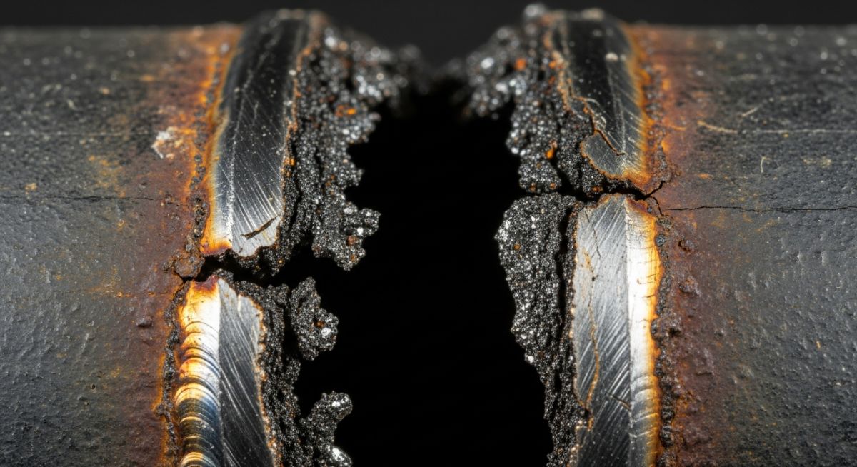
Background & Incident
In early 2026, a major petrochemical refinery experienced an unscheduled shutdown due to a high-pressure steam leak on a 3/4" NPS bypass line. The line utilized Class 3000 Socket Weld Pipe Fittings. Upon inspection, the leak was traced to a circumferential crack at the root of the fillet weld joining the pipe to a socket weld elbow. The system had been in service for less than 18 months under moderate thermal cycling.
Root Cause Analysis (RCA)
A metallurgical "cut-away" analysis revealed that the pipe had been "bottomed out" during installation. The mandatory 1.6mm (1/16 inch) expansion gap required by ASME B31.3 was completely absent. During startup and shutdown cycles, the pipe attempted to expand axially. Because it was already flush against the fitting shoulder, it had nowhere to go. This created extreme compressive stress on the fillet weld during heating and tensile stress during cooling. Over 400 cycles, this induced fatigue cracking that propagated from the internal root to the external surface.
Failure Data Summary
- Failing Component: 90° Elbow
- Standard: ASME B16.11
- Root Cause: Zero Expansion Gap
- Primary Mode: Thermal Fatigue
- Downtime Cost: $140,000+
Lessons Learned & Preventive Action
The facility overhauled its Quality Management System (QMS) to mandate pre-weld gap verification. All pipe fitters were re-trained on the "scribing method," where a mark is made on the pipe 1 inch from the socket, then checked after withdrawal to ensure exactly 1/16" of movement. For critical services, the use of Gap-A-Let rings was made mandatory to eliminate human error.
Expert Insights: Lessons from 20 years in the field
After two decades of overseeing piping installations in offshore and downstream environments, I have noticed that Socket Weld Pipe Fittings are often treated with less "respect" than large-bore butt welds. This is a mistake. Here are my hard-earned lessons:
- ● The "Scribe" Rule: Never trust a fitter who says they "felt" the 1/16 inch gap. Always require a scribe mark on the pipe at a set distance (e.g., 1 inch) from the fitting face. After welding, measuring the distance from the scribe to the face confirms if the gap was maintained.
- ● Vibration is the Enemy: Socket welds have an inherent stress concentrator at the root of the fillet weld. In systems with high vibration (near reciprocating compressors), these joints fail much faster than butt welds. Always consider additional gusseting or transitioning to butt welds in high-vibration zones.
- ● Material Matching: Ensure the fitting's forging grade matches the pipe exactly. Using a stainless steel Socket Weld Pipe Fitting on a carbon steel pipe without a specific transition procedure can lead to galvanic issues within the stagnant socket crevice.
- ● Post-Weld Heat Treatment (PWHT): For certain alloy steels, PWHT is required even for small-bore socket welds. Skipping this because "it is just a small pipe" is a leading cause of Stress Corrosion Cracking (SCC).
Frequently Asked Questions: Socket Weld Pipe Fittings
What is the difference between Class 3000 and Class 6000 Socket Weld Fittings?
Can Socket Weld Pipe Fittings be used in radioactive services?
Why is a 1.6mm (1/16") gap mandatory before welding?
Are socket weld fittings better than threaded fittings?
Can I perform Radiography (RT) on a socket weld?
What are the main materials used for these fittings?
📚 Recommended Resources: Socket Weld Pipe Fittings
Read these Guides
🎓 Advanced Training


Related posts:
![Piping stress engineer analyzing 3D piping model on computer screen for stress analysis]()
Mastering Piping Stress Interview Questions: The Ultimate Engineering Guide
![Industrial steam jet ejector 3D CAD model showing inlet and discharge ports]()
What is an Ejector? Types, Parts, Datasheet, and Working Principles
![3D CAD model of industrial piping system showing color-coded piping classes and specifications.]()
Mastering the Piping Material Specification for Industrial Plant Design
![Industrial pig launcher and receiver station with quick-opening closure and bypass piping.]()
Design and Engineering of Pig Launchers and Receivers
![Close-up of an industrial dial pressure gauge mounted on a stainless steel pipe.]()
What is a Pressure Gauge and How Does It Work?
![3D cutaway diagram of an industrial ball valve showing internal components like the ball, stem, and seats.]()
What is a Ball Valve? Design, Types, and Engineering Standards