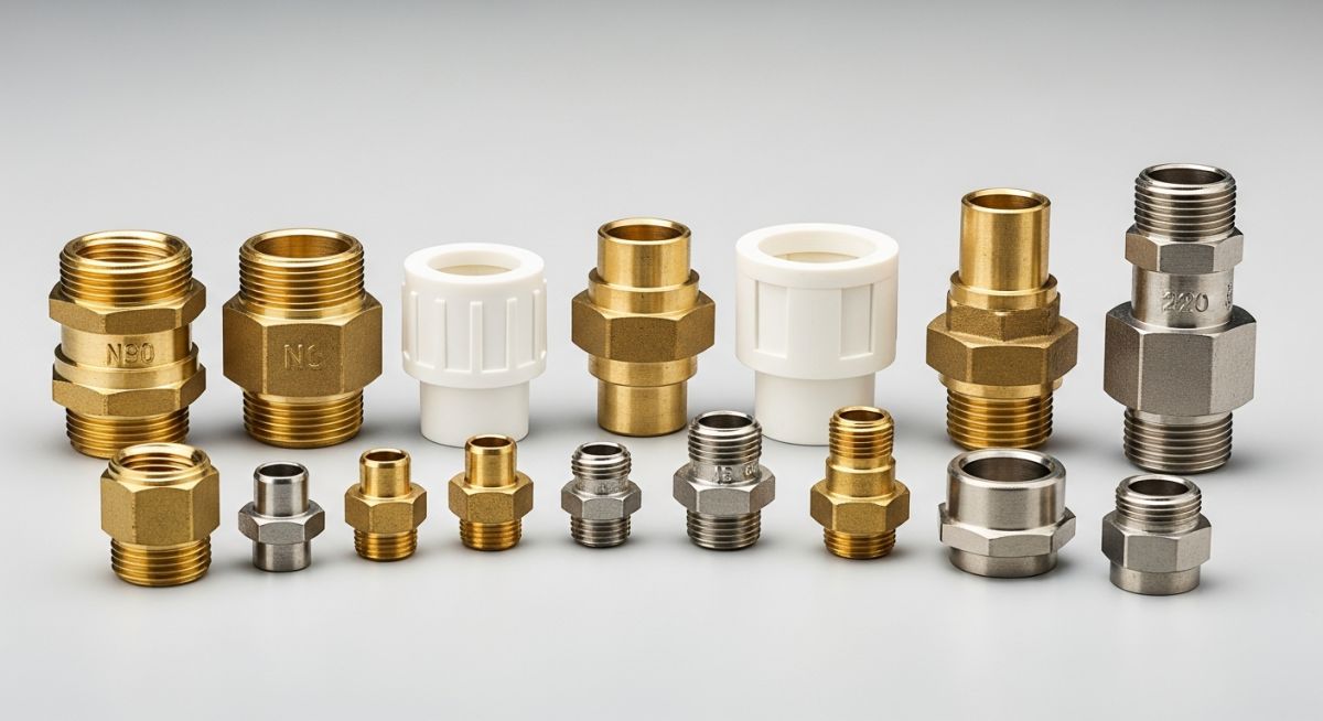
🛠️ EPCLAND WORKSPACE CONTROL PANEL ⚠️ DELETE THIS ENTIRE CONTAINER BOX BEFORE PUBLISHING THE BLOG POST Hero Image: Purpose: To visually introduce the concept of pipe adapters by showcasing a professional assortment of various adapter types and materials. Description: A clean, studio shot of various pipe adapters made of brass, PVC, and stainless steel arranged neatly on a neutral background, highlighting different thread types and connection ends. SEO Alt Text: An assortment of industrial pipe adapters in brass, stainless steel, and PVC. Image Slug: various-industrial-pipe-adapters Filename URL: https://epcland.com/wp-content/uploads/2026/06/various-industrial-pipe-adapters.jpg Technical Infographic: Purpose: To illustrate the anatomical differences between male and female adapters and how they transition between different connection types. Description: A detailed technical diagram showing a cross-section of a male-to-female pipe adapter, with labeled parts including threads, nominal diameter, and material thickness. SEO Alt Text: Technical diagram showing the cross-section and labeled parts of a pipe adapter. Image Slug: pipe-adapter-technical-diagram Filename URL: https://epcland.com/wp-content/uploads/2026/06/pipe-adapter-technical-diagram.jpg Meta Data: Focus Keyword: pipe adapter Title: What is a Pipe Adapter? Types, Materials, and Applications Slug: what-is-a-pipe-adapter Meta Description: Discover what a pipe adapter is, its key types, common materials, and industrial applications in piping systems. Tags: Pipe Adapter, Piping Systems, Pipe Fittings, Plumbing Materials, Industrial Engineering, Pipe Connections Author: Atul Singla | Piping Engineering Expert | Updated: May 2026 What is a Pipe Adapter and How to Select It Pipe Adapter Selection: A pipe adapter is a specialized piping component designed to connect two pipes of different sizes, materials, or end connection types while maintaining pressure containment and leak-tight integrity in compliance with ASME B31.3 and ASME B16.11 standards. In my 20+ years of managing high-pressure petrochemical piping installations, I have seen minor fitting mismatches shut down entire process lines. A pipe adapter is often the unsung hero of these systems, bridging the gap between incompatible piping runs. Whether you are transitioning from a threaded carbon steel header to a socket-welded stainless steel branch, or connecting a copper utility line to a plastic instrument manifold, selecting the correct adapter is the difference between a reliable system and a catastrophic field failure. Throughout my career, I have learned that understanding the nuances of thread profiles, material compatibility, and pressure ratings is not just academic—it is a safety requirement. In this guide, I will share my hands-on field experience to help you navigate the complex world of industrial adapters, their types, materials, and selection criteria. Key Engineering Takeaways Understand the structural differences between adapters and standard couplings. Learn how to calculate minimum wall thickness under ASME B31.3 rules. Identify the risks of galvanic corrosion when joining dissimilar metals. Master the field inspection steps to verify adapter integrity before pressure testing. Select the correct pressure class (2000#, 3000#, or 6000#) for your specific application. Interactive Engineering Quiz EPCLAND Portal Question 1 of 3 In industrial piping systems conveying electrolytes (such as water), connecting a copper alloy pipe to a galvanized steel pipe requires a specific adapter to prevent galvanic corrosion. Which type of adapter is engineered for this purpose, and what is its primary operating principle? A brass transition adapter that relies on the intermediate electrode potential of brass to buffer the galvanic reaction. A dielectric adapter containing an elastomeric or thermoplastic insulating insert that completely breaks the electrical conductivity between the two dissimilar metals. A stainless steel 316 adapter that acts as a sacrificial anode to protect both the copper and galvanized steel lines. A hot-dip galvanized malleable iron adapter that utilizes a high-thickness zinc coating to passivate the copper ions. Next Question → Question 2 of 3 When transitioning a piping system from a National Pipe Taper (NPT) connection to a British Standard Pipe Parallel (BSPP) connection using an adapter, which of the following statements correctly describes the sealing mechanism of the BSPP end of the adapter? It relies on metal-to-metal interference fit along the helical crests and roots of the mating threads. It requires a PTFE tape or thread sealant applied to the tapered flanks to fill the helical leak path. It seals via a 30-degree chamfered cone seat that deforms plastically upon torque application. It seals via an elastomeric bonded washer (Dowty seal) or an O-ring compressed against a flat mating surface. Next Question → Question 3 of 3 In high-pressure hydraulic systems subject to severe pressure spikes and mechanical vibration, O-Ring Face Seal (ORFS) adapters are often preferred over JIC 37-degree flare adapters. What is the primary technical reason for this preference? ORFS adapters allow for higher angular misalignment during installation compared to JIC adapters. The elastomeric O-ring in the ORFS adapter provides superior resistance to vibration-induced loosening and micro-movement leaks compared to the metal-to-metal seal of JIC. ORFS adapters require significantly lower assembly torque, reducing the risk of thread stripping in aluminum manifolds. The metal-to-metal contact in JIC adapters is highly susceptible to hydrogen embrittlement under high-velocity fluid flow. 🎉 Quiz Completed! You have passed the engineering review criteria. Core Technical Principles & Design Standards How Does a Pipe Adapter Function in Piping? Pipe Adapter Functionality: The primary role of a pipe adapter is to transition safely between dissimilar piping systems, such as joining male NPT threads to socket-weld runs or connecting copper tubing to carbon steel lines under ASME B31.1 design rules. To design a safe piping system, we must first distinguish between a coupling and an adapter. While a standard coupling joins two pipes of the same type and size, an adapter changes the connection style (e.g., male to female, threaded to welded) or joins entirely different materials. This transition introduces localized stress concentrations and potential leak paths that we must carefully analyze. Pressure Design Calculations under ASME B31.3 To determine the minimum required wall thickness of a forged carbon steel pipe adapter under internal pressure, we apply the design formula from ASME B31.3 Section 304.1.2: t = (P * D) / (2 * (S * E * W + P * Y)) Where: t = Minimum design wall thickness (inches) P = Internal design gage pressure (psi) D = Outside diameter of the adapter (inches) S = Allowable stress value for the material from ASME B31.3 Table A-1 (psi) E = Quality factor from ASME B31.3 Table A-1A or A-1B W = Weld joint strength reduction factor Y = Coefficient from ASME B31.3 Table 304.1.1 Let us calculate this for a 1-inch nominal ASTM A105 forged carbon steel adapter operating at 300 degrees Fahrenheit with a design pressure of 1000 psi. The outside diameter D is 1.315 inches. The allowable stress S for ASTM A105 at 300 degrees Fahrenheit is 20,000 psi. Assuming a seamless fitting, the quality factor E is 1.0, and the weld joint factor W is 1.0. For carbon steel at temperatures below 900 degrees Fahrenheit, the coefficient Y is 0.4. t = (1000 * 1.315) / (2 * (20000 * 1.0 * 1.0 + 1000 * 0.4)) t = 1315 / (2 * (20000 + 400)) t = 1315 / 40800 t = 0.0322 inches To find the nominal wall thickness, we must add a standard corrosion allowance (typically 0.0625 inches) and account for the manufacturer's undertolerance (usually 12.5 percent for forged fittings). This yields a robust, safe design that easily fits within standard Class 3000 dimensions. FIELD WARNING: Thread Engagement Risks Never mix NPT (National Pipe Thread) and BSPT (British Standard Pipe Taper) threads. While they may appear similar to an untrained eye, their thread pitches and angles differ. Forcing them together ruins the threads, compromises pressure containment, and leads to sudden joint separation under pressure. Common Types of Pipe Adapters In industrial systems, we categorize adapters based on their end configurations: Male vs. Female Adapters: Male adapters feature external threads, whereas female adapters have internal threads. These are used to connect threaded valves or instruments to the main run. Threaded-to-Welded Transitions: These allow a threaded instrument line to connect directly to a socket-weld or butt-weld piping system, maintaining structural strength. Flanged Adapters: Used to connect threaded or welded pipe runs directly to flanged equipment nozzles, complying with ASME B16.5. Engineering Dimensions & Pressure Ratings What Are the Standard Pipe Adapter Dimensions? Adapter Dimensional Standards: Pipe adapter dimensions are governed by ASME B16.11 for forged fittings and ASME B1.20.1 for pipe threads, ensuring precise thread engagement and wall thickness tolerances across all pressure classes. When specifying adapters for high-pressure systems, you must ensure that the fitting dimensions match the schedule of the mating pipe. Below is the dimensional data for Class 3000 forged carbon steel threaded adapters in accordance with ASME B16.11. Nominal Pipe Size (NPS) Outside Diameter (OD) (in) Min. Wall Thickness (in) Thread Engagement (L1) (in) Approx. Weight (lbs) 1/2" 1.12 0.125 0.32 0.45 3/4" 1.38 0.138 0.34 0.70 1" 1.75 0.162 0.40 1.15 1-1/2" 2.44 0.178 0.42 2.30 2" 3.00 0.219 0.44 3.90 Technical Mapping & Specifications Matrix This matrix maps specific adapter configurations to their corresponding material standards, pressure limits, and typical industrial applications. Adapter Type Material Grade Standard Reference Max Pressure Rating Primary Application Forged Carbon Steel ASTM A105 ASME B16.11 6000 psi High-pressure steam, oil, and gas lines Stainless Steel ASTM A182 F316 ASME B16.11 6000 psi Corrosive chemical processing, food & beverage Alloy Steel ASTM A182 F11/F22 ASME B16.11 3000 psi High-temperature power piping Brass ASTM B16 ASME B16.15 1000 psi Instrument air, water, and pneumatic lines PVC / CPVC Schedule 80 PVC ASTM D2467 150 psi Water treatment, low-pressure chemical lines Field Quality Control & Inspection How to Inspect a Pipe Adapter Onsite? Onsite Adapter Inspection: Field verification of a pipe adapter requires checking material test reports, verifying thread profiles against ASME B1.20.1 limits, and confirming pressure ratings before installation. Before any adapter is welded or threaded into a process line, it must undergo a rigorous quality control check. In my experience, skipping these basic steps is the leading cause of hydrotest failures. Use this checklist on your job site to ensure compliance. Onsite Inspection Checklist Material Test Report (MTR) Verification: Cross-reference the heat number stamped on the adapter body with the MTR to confirm chemical composition and mechanical properties match ASTM standards. Thread Profile Inspection: Inspect threads visually for nicks, burrs, or flat spots. Use a thread gauge to verify the pitch matches ASME B1.20.1. Pressure Class Verification: Confirm the pressure rating stamp (e.g., 3000# or 6000#) is clearly legible and matches the piping class sheet. Dielectric Isolation Check: If joining copper to steel, verify that the dielectric sleeve or gasket is present and undamaged to prevent galvanic corrosion. Dimensional Tolerances: Measure the socket depth and bore diameter to ensure they comply with ASME B16.11 limits before welding. Field Case Study & Engineering Analysis Field Case Study: Resolving Pipe Adapter Failures Field Failure Resolution: This case study examines how replacing incorrect thread profiles with code-compliant adapters resolved a chronic high-pressure steam leak at a chemical processing facility. The Problem: Chronic Steam Leaks and Shutdowns At a chemical processing plant, a 150 psi saturated steam line experienced repeated leaks at the transition between a carbon steel header and a stainless steel pressure transmitter. The field crew had installed a standard carbon steel threaded coupling with Teflon tape. Within three weeks of operation, the joint began leaking, causing a localized shutdown that cost the facility approximately 15,000 per day in lost production. The Solution: Engineering Redesign and Adapter Selection Upon investigation, I discovered two critical errors: first, the carbon steel coupling was experiencing accelerated galvanic corrosion due to direct contact with the stainless steel transmitter stem. Second, the thread sealant used was not rated for the 366 degrees Fahrenheit steam temperature. We replaced the coupling with an ASTM A182 F316 stainless steel socket-weld to NPT female adapter. We welded the socket end to the branch connection and used a high-temperature nickel-based anti-seize compound on the NPT threads. This eliminated the dissimilar metal contact and provided a robust, leak-tight seal. Direct Recommendation: Always perform a thermal and chemical compatibility check on both the adapter material and the thread sealant. For steam service above 300 degrees Fahrenheit, avoid standard Teflon tape and opt for high-temperature anaerobic sealants or nickel-filled compounds. Frequently Asked Engineering Questions Piping Adapter FAQs: This section addresses common engineering questions regarding pressure ratings, material compatibility, and installation standards for industrial adapters. What is the difference between a pipe adapter and a pipe coupling? A coupling is designed to connect two pipes of the same size and connection type (e.g., socket-weld to socket-weld). An adapter, however, transitions between different connection types (e.g., threaded to welded) or different materials, allowing incompatible systems to join safely under ASME B31.3 rules. How do you prevent galvanic corrosion when using a pipe adapter? To prevent galvanic corrosion when joining dissimilar metals (such as copper and carbon steel), you must install a dielectric adapter. This fitting contains an internal non-conductive polymer sleeve that electrically isolates the two metals, preventing the flow of corrosive galvanic currents. What ASME standards govern the design of a pipe adapter? Forged metal adapters are governed by ASME B16.11, which specifies dimensions, ratings, and materials. The threaded ends must comply with ASME B1.20.1 for NPT profiles. Can a pipe adapter be used in high-pressure hydraulic systems? Yes, but you must specify high-pressure forged steel adapters rated for Class 6000 or Class 9000 service. Standard plumbing-grade adapters are limited to low-pressure utility lines and will fail under hydraulic shock loads. How do you calculate thread engagement for NPT adapters? Thread engagement is determined by the L1 dimension in ASME B1.20.1. For example, a 1-inch NPT thread requires a minimum hand-tight engagement of 0.40 inches, followed by 2 to 3 full turns with a wrench to achieve a leak-tight seal. When should you choose a socket-weld adapter over a threaded adapter? Socket-weld adapters are preferred for systems subject to high vibration, thermal cycling, or hazardous fluids where threaded joints present a leak risk. Threaded adapters are ideal for instrument connections, utility lines, and systems requiring frequent disassembly. ===