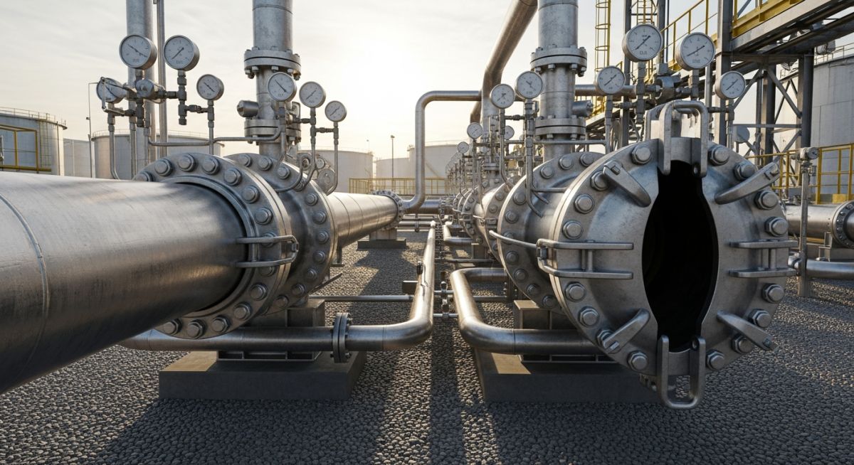
🛠️ EPCLAND WORKSPACE CONTROL PANEL ⚠️ DELETE THIS ENTIRE CONTAINER BOX BEFORE PUBLISHING THE BLOG POST Hero Image: Purpose: To visually introduce a high-quality industrial pig launcher and receiver system installed on an active pipeline site. Description: A high-resolution 3D render of an industrial pig launcher and receiver station, showcasing the major barrel, quick-opening closure, bypass piping, and pressure gauges in an outdoor oil and gas facility. SEO Alt Text: Industrial pig launcher and receiver station with quick-opening closure and bypass piping. Image Slug: industrial-pig-launcher-receiver-station Filename URL: https://epcland.com/wp-content/uploads/2026/06/industrial-pig-launcher-receiver-station.jpg Technical Infographic: Purpose: To illustrate the anatomical components, valves, and flow path of a standard pipeline pig launcher. Description: A detailed engineering schematic diagram labeling the key components of a pig launcher, including the nominal line, major barrel, reducer, quick-opening closure, kicker line, pressure gauge, and drain valves. SEO Alt Text: Schematic diagram showing the components and flow path of a pipeline pig launcher. Image Slug: pig-launcher-schematic-diagram Filename URL: https://epcland.com/wp-content/uploads/2026/06/pig-launcher-schematic-diagram.jpg Meta Data: Focus Keyword: pig launchers and receivers Title: Guide to Pig Launchers and Receivers in Pipeline Pigging Systems Slug: pig-launchers-and-receivers Meta Description: Learn the design, operation, and safety standards of pig launchers and receivers used in pipeline pigging systems. Tags: pipeline engineering, pig launchers, pig receivers, pipeline pigging, oil and gas piping, pig traps, pipeline maintenance Focus Keyword: pig launchers and receivers Title: Design and Engineering of Pig Launchers and Receivers Slug: pig-launchers-and-receivers Meta Description: Master the design, operation, and safety standards of pig launchers and receivers in pipeline systems under ASME B31.4 and B31.8 codes. Tags: pipeline engineering, pig launchers, pig receivers, pipeline pigging, oil and gas piping, pig traps, pipeline maintenance Author: Atul Singla | Piping Engineering Expert | Updated: May 2026 Design and Engineering of Pig Launchers and Receivers Pig Launchers and Receivers: These specialized pressure vessels and piping assemblies facilitate the safe insertion and retrieval of pipeline pigs into active hydrocarbon or utility pipelines under full operating pressure in compliance with ASME B31.4, ASME B31.8, and ASME Section VIII Division 1. In my 20 years of commissioning pipeline systems across the globe, I have seen many young engineers treat pig traps as simple, oversized pipes. That is a dangerous mistake. These components are highly engineered pressure vessels subject to severe cyclic stresses, thermal expansion, and unpredictable dynamic forces during pig transit. Whether you are clearing paraffin wax from a crude line or running an intelligent magnetic flux leakage (MFL) tool to detect corrosion, the design of your launcher and receiver station dictates the safety of your entire field crew. When a pig travels at 5 meters per second and hits a receiver barrel, the kinetic energy transfer is immense. If your bypass lines, kicker lines, and quick-opening closures are not engineered with precision, you risk catastrophic pressure containment loss. In this guide, I will walk you through the exact design calculations, code requirements, and field realities that I use to design safe, high-performance pigging stations. Key Engineering Takeaways Understand the critical dimensional differences between major and minor barrels. Master the wall thickness calculations under ASME B31.4 and B31.8 codes. Learn how to size kicker, bypass, and drain lines to prevent pig stalling. Implement mandatory safety interlocks on quick-opening closures to protect field operators. Interactive Engineering Quiz EPCLAND Portal Question 1 of 3 What is the primary code-mandated safety design requirement for Quick Opening Closures (QOC) installed on pig launchers and receivers to prevent catastrophic failure during operation? A pressure warning device that alerts the operator via SCADA but does not physically restrict the opening mechanism. A mechanical safety interlock system that prevents the closure from being opened until the internal pressure has been completely relieved to atmospheric pressure. A dual-valve bypass system that automatically opens when the closure door handle is touched. A rupture disk rated at 110% of the design pressure installed directly on the closure door. Next Question → Question 2 of 3 When designing a pig launcher for intelligent (ILI) tools, why is an eccentric reducer (flat on bottom) typically preferred over a concentric reducer, and what is the standard major barrel sizing rule of thumb? Concentric reducers cause liquid pooling; the major barrel should be at least 4 inches larger than the nominal pipeline size for pipelines $\ge$ 12 inches. Eccentric reducers (flat on bottom) maintain a continuous bottom-of-pipe (BOP) elevation to prevent the heavy ILI tool from getting stuck or damaged during loading; the major barrel is typically 2 nominal sizes larger than the pipeline. Eccentric reducers (flat on top) prevent gas pockets; the major barrel must be exactly the same ID as the pipeline to maintain seal integrity. Concentric reducers are preferred to balance flow distribution; the major barrel must be 1.5 times the length of the ILI tool but the same diameter. Next Question → Question 3 of 3 In a standard pig receiver configuration, where should the kicker (bypass) line connection be physically located on the barrel, and what is its primary operational purpose during the receiving sequence? Located at the front of the major barrel near the reducer; its purpose is to inject high-pressure gas to push the pig back into the main line if it overshoots. Located at the rear of the major barrel near the closure; its purpose is to vent the entire receiver volume to the flare system before opening. Located on the major barrel near the closure (rear); its purpose is to draw flow through the receiver to pull the incoming pig completely past the nominal line tee and into the receiver barrel. Located on the minor barrel; its purpose is to equalize pressure across the pig cup seals to prevent them from tearing during extraction. 🎉 Quiz Completed! You have passed the engineering review criteria. Core Design Methodology & Sizing Calculations How to Design Pig Launchers and Receivers Pig Trap Sizing: The engineering of pig launchers and receivers requires precise calculation of the major barrel, minor barrel, and transition reducer to ensure safe pig transit and pressure equalization under ASME B31.4 and ASME B31.8 standards. The physical geometry of a pig trap is divided into two primary sections: the major barrel (the oversized section where the pig is loaded or retrieved) and the minor barrel (which matches the nominal pipeline diameter). Connecting these two sections is a concentric or eccentric reducer. 1. Barrel Diameter Sizing The major barrel diameter must be larger than the nominal pipeline diameter to allow the pig to be easily inserted (in launchers) or to allow the bypass fluid to flow around the pig as it comes to a stop (in receivers). For pipelines up to 10 inches: The major barrel diameter is typically 2 inches larger than the nominal pipeline size. For pipelines 12 inches and larger: The major barrel diameter is typically 4 inches larger than the nominal pipeline size to accommodate heavy intelligent pigs and cup deflection. 2. Barrel Length Sizing The length of the major barrel depends on the type of pigs you plan to run. Standard utility pigs (foam, cup, or brush pigs) are relatively short. However, intelligent inspection tools (smart pigs) require significantly longer barrels due to their multi-module sensor arrays. The formula I use to determine the minimum major barrel length (Lm) for a launcher is: Lm = (1.5 * L_pig) + Clearance Where L_pig is the length of the longest intelligent pig expected to be used during the pipeline's design life. For receivers, the major barrel length is typically longer to allow for debris accumulation ahead of the pig: Lm_receiver = (2.0 * L_pig) + Clearance 3. Wall Thickness Calculations Because pig traps are located at pipeline terminals, they are subject to the design codes of the adjacent pipeline. For liquid pipelines, we design under ASME B31.4. For gas pipelines, we design under ASME B31.8. The nominal wall thickness (t) of the major barrel is calculated using the Barlow's formula modified by the design factors: t = (P * D) / (2 * S * F * E * T) Where: P = Internal design pressure (psig or barg) D = Outside diameter of the major barrel (inches or mm) S = Specified Minimum Yield Strength (SMYS) of the steel (psi or MPa) F = Design factor (typically 0.60 or 0.50 for terminal piping near stations, depending on location class) E = Longitudinal joint factor (1.0 for seamless or high-quality submerged arc welded pipe) T = Temperature derating factor (1.0 for operating temperatures below 250°F / 121°C) CRITICAL FIELD WARNING: Never use the standard pipeline design factor (such as 0.72) for the major barrel. Because the major barrel is subjected to frequent pressure cycling, venting, and dynamic mechanical impacts during pig loading and unloading, a conservative design factor of 0.50 or 0.60 must be applied to prevent fatigue cracking around the nozzle welds. 4. Kicker and Bypass Line Sizing The kicker line is the piping that diverts flow from the main pipeline into the back of the pig launcher to push the pig forward, or diverts flow from the receiver to pull the pig in. In my experience, sizing the kicker line too small is the leading cause of stalled pigs. The kicker line should be sized to handle at least 30% to 50% of the total pipeline flow rate. For gas lines, the velocity in the kicker line should not exceed 20 meters per second to prevent severe vibration and erosion. Standard Dimensional Specifications Below is the standard engineering dimension matrix that I have developed over years of executing pipeline projects. These dimensions serve as an excellent starting point for front-end engineering design (FEED) packages. Nominal Pipe Size (inches) Major Barrel Size (inches) Launcher Major Length Lm (mm) Receiver Major Length Lm (mm) Kicker Line Size (inches) 6 8 1200 1800 2 12 16 1800 2400 4 24 28 2800 3600 8 36 40 3500 4800 12 Technical Mapping & Specifications Matrix This matrix maps the core technical entities, structural acronyms, and physical parameters of pig traps to their governing international standards. Component / Parameter Acronym Primary Function Governing Code / Standard Quick Opening Closure QOC Provides rapid access to the barrel for loading/retrieval ASME Sec VIII Div 1 / UG-35.2 Pig Signaller / Indicator PIGSIG Detects the physical passage of the pig past a specific point Manufacturer Standard / API 6D Specified Minimum Yield Strength SMYS Defines the plastic deformation limit of the steel barrel API Spec 5L / ASTM A106 Pressure Safety Valve PSV Protects the barrel from overpressurization during isolation ASME Sec VIII Div 1 Site Verification Checklist Pre-Commissioning Checklist for Pig Launchers and Receivers Pre-Commissioning Verification: Field validation of pig traps ensures structural integrity, pressure containment, and operational safety through rigorous testing of quick-opening closures, safety interlocks, and instrument alignments before introducing hydrocarbons. Before you sign off on a newly installed pig launcher or receiver station, you must perform a comprehensive field walkdown. Below is the exact checklist I use to verify that the installation matches the engineering design and is safe for live operations. Field Inspection & Commissioning Protocol Verify QOC Safety Interlock: Ensure the mechanical safety interlock on the quick-opening closure is fully functional. The interlock must physically prevent the door from opening if there is any residual pressure (even as low as 0.05 barg) inside the barrel. Check Reducer Orientation: For pig receivers, verify that an eccentric reducer is installed with the flat side on the bottom (flat-on-bottom). This prevents liquids and debris from pooling at the transition point, which can cause localized corrosion. Inspect Pig Signaller Alignment: Ensure the mechanical trigger or non-intrusive magnetic sensor of the pig signaller is positioned correctly. Intrusive triggers must be checked for correct insertion depth to prevent them from being sheared off by the pig. Validate Vent and Drain Routing: Confirm that the barrel vents are routed to a safe location (flare or high-point vent) and that the drains are routed to the closed drain system. Drains must never be discharged directly to the ground. Confirm Grounding and Bonding: Verify that the launcher/receiver barrel is electrically bonded to the main pipeline and connected to the facility grounding grid to prevent static electricity buildup during pigging operations. Field Case Study Field Case Study: Real-World Application The Problem: Pig Stalling and Pressure Spikes in a Wet Gas Line During the commissioning of a 24-inch wet gas pipeline in the Middle East, the field operators experienced repeated pig stalling inside the receiver's minor barrel. When the pig stalled, the upstream pressure rapidly spiked by 15 barg, threatening to trigger an emergency shutdown (ESD) of the upstream production facility. Upon investigation, I discovered that the original engineering design had specified a kicker line that was only 4 inches in diameter (less than 17% of the main pipeline size). This restricted the bypass flow rate, leaving insufficient differential pressure across the pig to push it through the concentric reducer into the major barrel. The Outcome: Redesigning the Kicker System for Safe Operations To resolve this issue without replacing the entire receiver vessel, I led a fast-track engineering modification. We hot-tapped the receiver to install an auxiliary 8-inch kicker line, effectively increasing the bypass flow capacity to 40% of the total pipeline flow. We also replaced the standard concentric reducer with an eccentric flat-on-bottom reducer during a scheduled maintenance shutdown. This modification allowed the heavy liquids swept by the pig to drain freely into the liquid collection system rather than pooling at the reducer face. Direct Recommendation: Always size your kicker lines for a minimum of 30% of the maximum design flow rate, and utilize eccentric flat-on-bottom reducers for receivers to prevent liquid accumulation and pig stalling. Frequently Asked Engineering Questions What is the difference between a pig launcher and a pig receiver? A pig launcher is designed to insert a pig into a pressurized pipeline. It features a kicker line connected to the rear of the major barrel to push the pig forward. A pig receiver is designed to receive and retrieve the pig. It features a kicker line connected near the reducer to pull the pig into the major barrel while allowing the main fluid flow to bypass the pig. Why are eccentric reducers preferred over concentric reducers for pig receivers? Eccentric reducers installed with the flat side on the bottom (flat-on-bottom) are preferred for receivers because they prevent liquids, wax, and debris from pooling at the transition point. This ensures smooth pig transit and allows complete drainage of the barrel, reducing the risk of localized corrosion. Which ASME codes govern the design of pig launchers and receivers? The piping and overall station layout are governed by ASME B31.4 for liquid pipelines and ASME B31.8 for gas pipelines. The quick-opening closure (QOC) and the major barrel pressure vessel components are designed in accordance with ASME Section VIII Division 1. What is the purpose of a kicker line in a pigging system? The kicker line is a bypass line that directs pressurized fluid behind the pig in a launcher to create the differential pressure required to launch it. In a receiver, the kicker line is used to draw fluid from the barrel, creating a pressure differential that pulls the incoming pig completely into the receiver barrel. How do safety interlocks work on quick-opening closures? Safety interlocks are mechanical or key-controlled systems that prevent the operator from opening the door of the quick-opening closure (QOC) while the barrel is pressurized. The interlock typically consists of a pressure warning device that must be manually unscrewed to vent any residual pressure before the main locking ring can be disengaged. Why is a balance line required on a pig receiver? A balance line connects the kicker line to the front of the receiver barrel. It equalizes the pressure on both sides of the pig once it has arrived in the major barrel. This prevents the pig from moving unexpectedly when the isolation valves are closed and venting operations begin. ===FAQ_BLOCK===