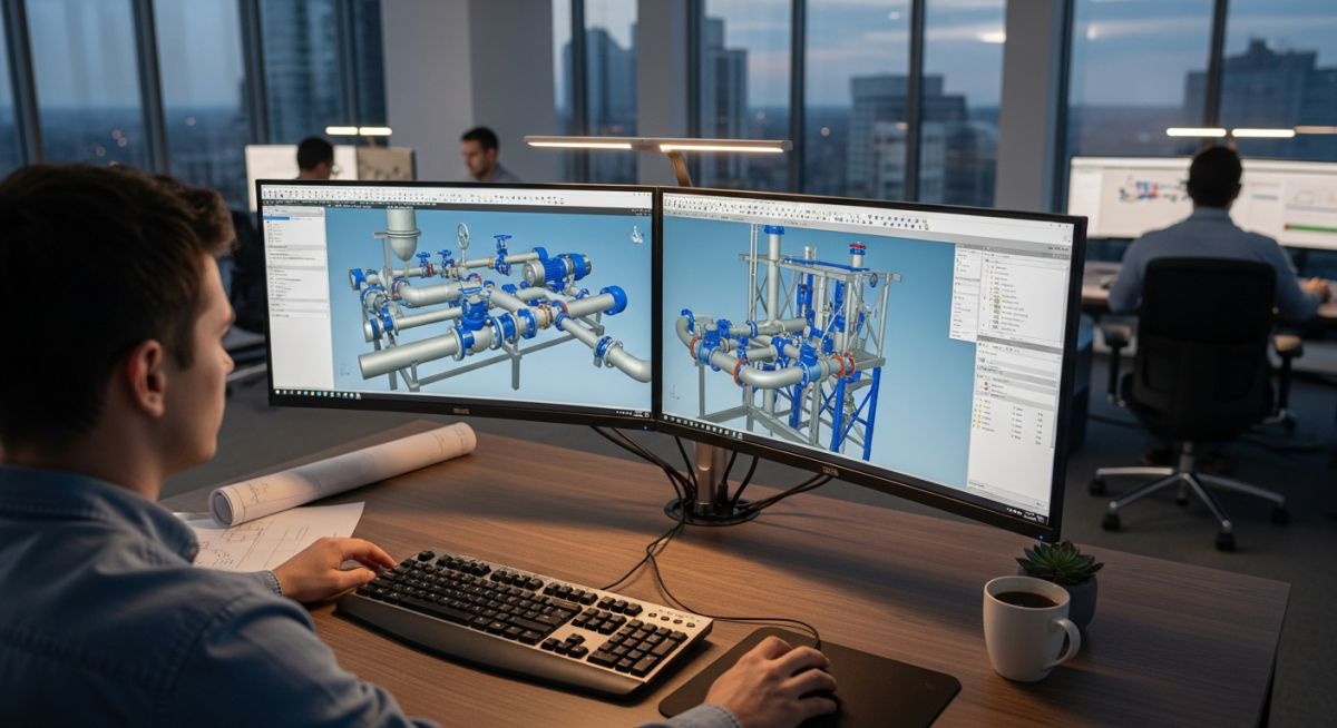
Industrial engineer designing a 3D piping system on a computer in an Indian engineering firm.
Author: Atul Singla | Piping Engineering Expert | Updated: July 2026
Industrial piping design engineering in India

Selecting the Best Piping Design Companies in India for Projects

Piping Design Engineering Services: The specialized engineering workflow encompassing 3D plant modeling, stress analysis, and isometric extraction executed in compliance with ASME B31.3 and ASME B31.1 standards. These services ensure structural integrity, thermal flexibility, and optimal fluid dynamics across complex industrial process plants.

In my 20 years of managing multi-billion dollar refinery and petrochemical projects, I have seen how a single piping design error can derail an entire construction schedule. India has emerged as a global powerhouse for engineering design, hosting some of the most sophisticated engineering centers in the world. When you partner with engineering firms in this region, you are not just outsourcing drafts; you are integrating highly specialized technical minds into your project lifecycle.

Key Takeaways for Project Managers:

  • Technical compliance with ASME B31.3 and ASME B31.1 is non-negotiable for global safety standards.
  • Advanced 3D modeling tools like SP3D and E3D must be paired with rigorous stress analysis in CAESAR II.
  • Indian engineering hubs offer significant cost advantages while maintaining world-class quality standards.


Interactive Engineering Quiz
EPCLAND Portal
Question 1 of 3

In major Indian piping design engineering centers (such as EIL, L&T Hydrocarbon, and Toyo India), CAESAR II is widely utilized for piping stress analysis per ASME B31.3. When calculating the allowable displacement stress range (Sa) for a system where the principal sustained longitudinal stress (SL) is not fully utilized, which formula represents the “liberal” allowable stress range according to ASME B31.3?


Technical Evaluation and Engineering Standards

Evaluating Piping Design Companies in India

Engineering Evaluation Criteria: The systematic assessment of technical competencies, software proficiencies, and quality assurance protocols required to select an engineering partner. This process guarantees compliance with international design codes such as ASME, API, and EN.

When evaluating engineering partners, I look beyond their headcount. The true measure of capability lies in their understanding of stress analysis, thermal expansion, and structural integrity. High-temperature and high-pressure piping systems require rigorous mathematical validation to prevent catastrophic failures in the field.

Thermal Expansion and Stress Analysis Calculations

A core capability of top-tier design firms is their proficiency in calculating displacement stress ranges. According to ASME B31.3 Section 319.4.4, the computed displacement stress range SE must not exceed the allowable displacement stress range SA.

The displacement stress range is calculated using the following formula:

SE = square root of (Sb squared + 4 times St squared)

Where:

  • Sb is the resultant bending stress.
  • St is the torsional stress.

The allowable displacement stress range SA is defined as:

SA = f times (1.25 times Sc + 0.25 times Sh)

Where:

  • f is the stress range reduction factor for cyclic conditions.
  • Sc is the basic allowable stress at the minimum metal temperature.
  • Sh is the basic allowable stress at the maximum metal temperature.
Field Warning: Never accept stress analysis reports that do not clearly define the boundary conditions, friction coefficients, and wind or seismic load cases. In my experience, many low-cost service providers skip the dynamic analysis of reciprocating compressor piping, leading to catastrophic fatigue failures during commissioning.
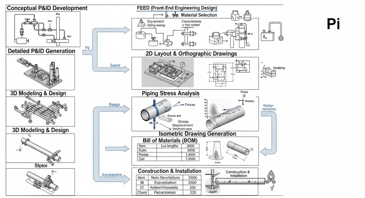
Piping engineering design workflow chart

The workflow chart above illustrates the critical feedback loop between 3D modeling and stress analysis. A failure to integrate these two disciplines often results in costly field modifications and construction delays.

Technical Deliverables and Software Standards
Deliverable Type Industry Standard Primary Software Key Engineering Output
3D Plant Layout ASME B31.3 SP3D, Aveva E3D Clash-free spatial routing and equipment positioning.
Stress Analysis ASME B31.1 CAESAR II, AutoPIPE Nozzle load reports, spring hanger selections, and displacement checks.
Piping Isometrics ASME Y14.3 Isogen, SmartIsometrics Fabrication-ready drawings with complete Bill of Materials (BOM).

Technical Mapping & Specifications Matrix
Entity / Acronym Technical Definition Physical Parameter / Limit Standard Reference
NPS (Nominal Pipe Size) Dimensionless designator for pipe size based on nominal diameter. NPS 0.5 to NPS 60 and above. ASME B36.10M
WT (Wall Thickness) The physical thickness of the pipe wall required to withstand internal pressure. Calculated based on hoop stress limits. ASME B31.3 Section 304
CA (Corrosion Allowance) Additional wall thickness added to account for material loss over design life. Typically 1.5 millimeters to 3.0 millimeters. Project Specific Design Basis

Engineering Quality Audit Checklist

Design Quality Verification

Design Quality Verification: The structured audit process used to validate engineering deliverables against project design bases and international standards. This protocol ensures that all isometric drawings, stress reports, and support designs are error-free before construction.

Before approving any deliverables from your engineering partner, I highly recommend executing a rigorous quality audit. Below is the checklist I use during my project reviews to ensure technical compliance and minimize field rework.

Site Verification Checkpoints:


  • Verify that the design pressure and temperature match the latest Process Flow Diagram (PFD) and Piping and Instrumentation Diagram (P&ID).

  • Confirm that all high-temperature lines (above 120 degrees Celsius) have undergone formal flexibility analysis in CAESAR II.

  • Ensure that the minimum straight run requirements for flow meters and control valves comply with ISA standards.

  • Check that the piping support span does not exceed the maximum allowable limits specified in MSS SP-58.

  • Validate that the material selection and corrosion allowance align with the project-specific piping class specifications.

Field Case Study: Real-World Application

Capabilities of Piping Design Companies in India

Technical Execution Capabilities: The specialized engineering competencies required to execute complex piping layouts, stress analysis, and material specifications for high-pressure, high-temperature industrial systems. These capabilities ensure safe, reliable, and cost-effective plant operations.
The Problem: A major European chemical plant expansion faced severe delays due to thermal expansion issues in a high-pressure steam line. The original design failed to account for the dynamic loads of a steam hammer, resulting in excessive nozzle loads on the steam turbine.
The Outcome: I collaborated with a leading engineering team in India to redesign the piping layout. By utilizing advanced CAESAR II dynamic analysis and introducing custom spring hangers and structural struts, we reduced the nozzle loads by 65 percent. The project was completed 3 weeks ahead of the revised schedule, saving over 250,000 USD in potential downtime.

I highly recommend conducting a joint technical review meeting between your in-house engineering team and the Indian design partner at the 30 percent, 60 percent, and 90 percent model review stages to ensure seamless alignment.

Frequently Asked Engineering Questions

What are the primary design codes used by piping design companies in India?

Indian engineering firms strictly adhere to international standards, primarily ASME B31.3 for process piping, ASME B31.1 for power piping, and ASME Section VIII for pressure vessel design. They also design in compliance with European standards (EN 13480) and regional codes depending on the project location.
How do engineering firms in India handle seismic and wind load calculations?

Seismic and wind loads are calculated using local building codes such as ASCE 7, IBC, or NBC. These parameters are input directly into stress analysis software like CAESAR II to evaluate the structural response of the piping system and design appropriate restraints.
What software tools are standard for 3D piping design and stress analysis?

The industry standards include Intergraph Smart 3D (SP3D), Aveva Everything3D (E3D), and Autodesk AutoCAD Plant 3D for modeling. For stress analysis, CAESAR II and Bentley AutoPIPE are the most widely accepted tools.
How is the quality of isometric drawings ensured before fabrication?

Quality is maintained through a multi-stage review process. This includes automated clash detection in Navisworks, manual checking against the P&ID, and verification of the Bill of Materials (BOM) against the piping class specifications.
What is the typical workflow for a piping stress analysis project?

The workflow begins with data collection (line list, piping spec, and equipment drawings). Next, critical lines are identified for formal analysis. The piping geometry is modeled in CAESAR II, loads are applied, and the system is optimized by adjusting support locations until all code requirements are met.
Why should global companies outsource piping design to India?

India offers a unique combination of highly skilled, English-speaking engineering talent, advanced software infrastructure, and significant cost efficiencies. The time-zone difference also allows for a round-the-clock engineering execution model, accelerating project schedules.